


Applying Normal Bump Maps
to Objects
In this lesson, you will apply the normal bump map you created in the previous lesson to the low-resolution model of the warrior.
 open warrior_head_b_map.max.
 Select the low-resolution
version of the head by clicking a checkered portion of the model,
then go to the
Select the low-resolution
version of the head by clicking a checkered portion of the model,
then go to the  Modify panel.
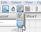
 Slate Material Editor.
 (Assign Material To Selection).
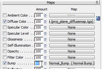
On the file dialog, choose head_diffuse.jpg (this file is in the \sceneassets\images folder).
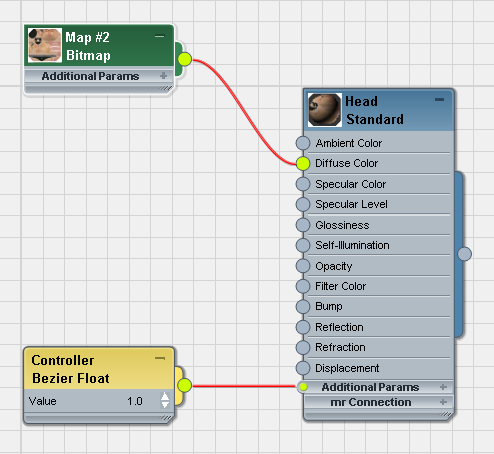
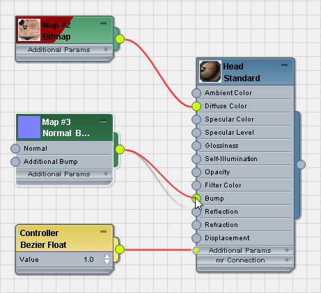
When you wire the Bitmap, 3ds Max adds a Controller node for the bitmap’s Value.
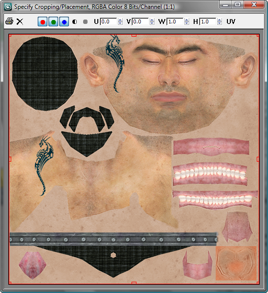
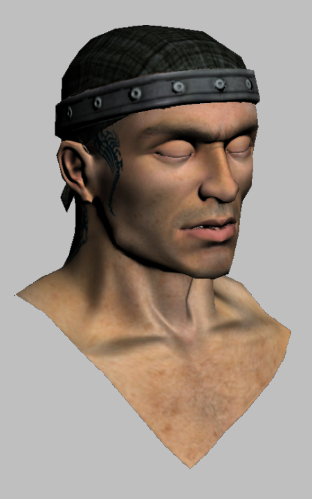
This image file is a previously created diffuse bitmap of the warrior’s face, based on the unwrapped model.
 Close the image window.
 (Show Map In Viewport) to
see the material in viewports.
(Show Map In Viewport) to
see the material in viewports.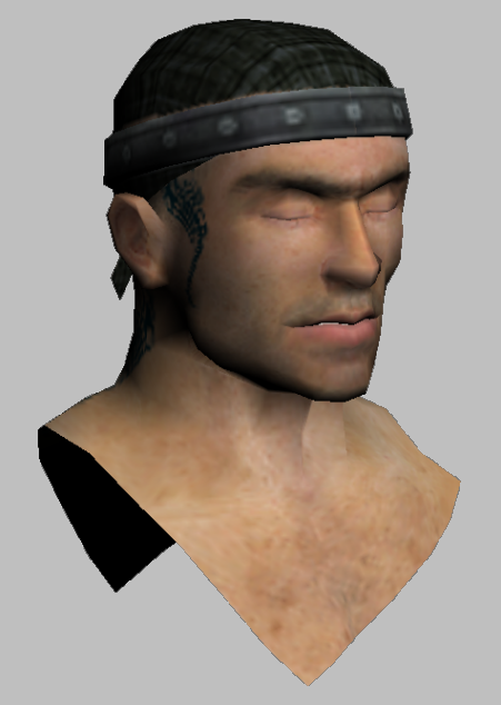
The result is fairly flat and lacking in detail. The normal bump map you will now apply should improve things considerably.
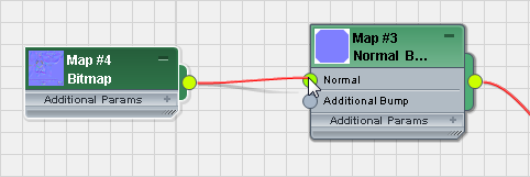
Use a Normal Bump map to apply the normal map:
On the file dialog, choose war_head_loresnormalsmap.tga, (this file is in the \sceneassets\images folder).
(If you like, you can use the version of this map that you rendered yourself in the previous lesson.)
Now the normal bump map will be visible in renderings. To make the normal bump map visible in viewports, you need to go through a few more steps.
Use hardware shading to display the normal bump map:
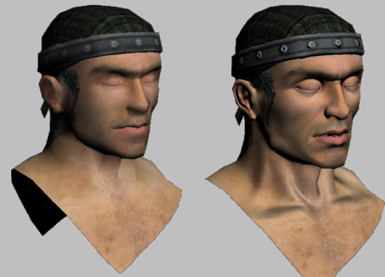
If you like, try adding an Omni light to the scene and moving the light object across the face: first with the diffuse map selected, then with the normal bump map selected. See how much of a difference a normal bump map can make.
Compared to the head that doesn’t use the normal bump map, the difference is dramatic.
This tutorial showed you how to use a projection cage to receive texture from a high-resolution model, then apply the result to a low-resolution version of the same model. This technique is an effective way to assign complex surface detail to low-polygon objects. This can be a useful technique when you prepare a model for a game engine. It can help improve render time, as well.