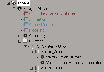
Before you can paint colors on an object's vertices, you need to create a Color at Vertices (CAV) property — or map — on the object. The CAV property acts as an invisible support object on the selection that accepts the vertex painting. A polygon object can have multiple CAV properties, but can only display one at a time (see the following section, Choosing a CAV Property to Display).
Although renaming a CAV property is an easy task, it can seem complicated when you are using it to drive several different elements. For example, several shaders and RenderVertex properties might all reference the same CAV.
Fortunately, it's easy to update all of these references automatically when you rename the CAV. You can specify if and how the references are updated.
In the explorer, locate the CAV that you wish to rename.
In the Vertex Color property editor, click the Rename button to open the Rename Vertex Color dialog box.
Enter the new name for the CAV in the New Name text box.
Spaces and other illegal characters are automatically converted to underscores. If the name already exists, a number is automatically appended to preserve uniqueness.
Use the following options to control how references to the CAV are updated:
Update references to the property searches for shaders, rendermaps, CAV maps, and materials that refer to the old name of the property explicitly (that is, without using wildcards), and updates them to use the new name.
Update references containing wildcards searches for property references containing wildcards that resolve to the old name, and tests whether they still resolve to the new name. If they do not resolve to the new name, the references are updated.
For example, suppose you are using a naming convention such as skin_objectname for your CAV maps, and using the wildcard expression skin_* to match it in shader trees. If you change the name of the CAV map skin_belly to skin_abdomen, the wildcard expression still matches the new name so the reference is not changed. If you change the name of the map to tummy_skin, the wildcard expression does not match so the reference is updated.
Click OK to close the dialog box, rename the CAV, and update the references.
You can only paint on an object's active CAV property. If you've applied more than one CAV property to an object, you need to make sure which one is currently displayed by the object's material before you start painting vertices.
Polygon clusters with local materials always display the CAV property of their local material. However, the CAV property that is active for painting is still the one specified in the object's material.
Select an object to which multiple CAV properties are applied.
From the Select panel in the main command panel, click the Selection button. A pop-up explorer opens, displaying the object's hierarchy.
Click the object's material node icon to open its Material property editor.
From the Material property editor, select a CAV property from the Vertex Color Display Property list.
The selected CAV property becomes the material's active CAV property — the one that is affected when you paint colors on the object.
While the Paint Vertex Color tool is active, viewports under the mouse pointer temporarily change to Constant if they are currently in Wireframe mode. Otherwise, they use their current display mode. This makes it easier to see the results while still allowing you to use vertex colors to, for example, drive texture blending factors with a pixel shader.
Press R and drag the mouse to change the brush radius interactively. You can also set the radius on the weight paint panel. For additional ways to set the radius, see Changing the Brush Radius [Commands and Tools].
Press E and drag the mouse to change the opacity interactively. The opacity controls how much color is added with each stamp of the brush.
Set other options in the Brush Properties Property Editor (Ctrl+W).
You can paint on CAV properties using either the Brush method or the Raycast method.
From the Vertex Color tab, set the Color Paint Method to one of the following:
The Brush method uses a virtual paint brush to paint colors at vertices. Vertices within the brush radius are painted in accordance with the current Color Paint Mode (see Setting a Color Paint Mode) and the other brush settings.
Painting with the brush always applies the brush stamp as if vertex bleeding is on (see Using Polygon/Vertex Bleeding (Raycast Mode Only)).
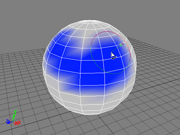
When the brush is activated, the mouse cursor changes to a representation of the brush radius with an arrow pointing outward from the center, in the direction of the normal.
You can adjust the brush's radius, opacity, and a variety of other settings described in Setting Brush Properties. The brush method obeys all of these settings.
The Raycast method paints on vertices that are directly beneath the mouse cursor, in accordance with the brush's opacity and spacing settings (see Setting Brush Properties).
You can activate vertex and /or polygon bleeding to extend the brush stamp (see Using Polygon/Vertex Bleeding (Raycast Mode Only)).
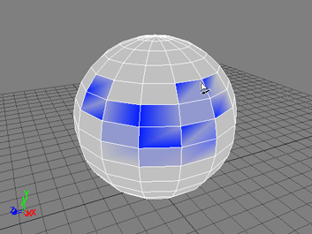
As you paint the surface of an object, you will notice that the area being colored is triangular. This area corresponds to the triangles (polynodes) that make up the polygon object you are working on.
But rather than coloring triangles, you can use the Color at Vertices tool to bleed your paintbrush selection onto vertices, entire polygons, or both. When using bleeding, the effect is immediately visible in the viewport in which you are painting.
Beneath the Opacity slider, you can select the Vertex Bleeding or Polygon bleeding option (or both) to extend your paintbrush selection.
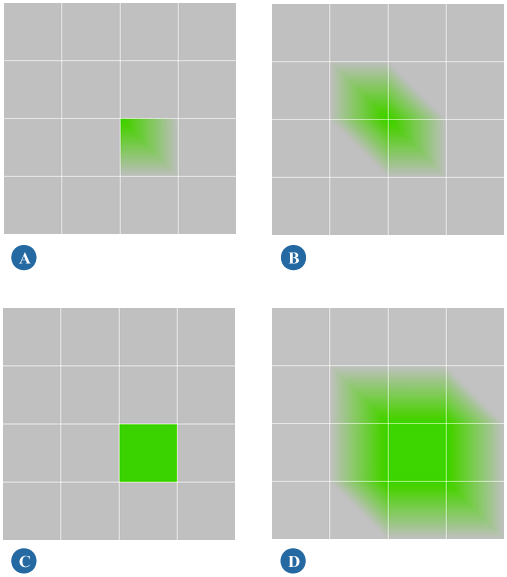
All of the examples above have had the same point clicked once. They show how a single click can extend a selection with no bleeding, vertex bleeding, polygon bleeding, or both vertex and polygon bleeding.
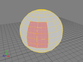
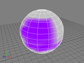
When you're painting on an object's CAV property, you can select a subset of the object's polygons and either restrict the paint strokes to that subset, or exclude them from it.
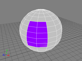
Make a polygon selection on the object whose vertices you wish to paint.
Press Ctrl+W to open the Brush Properties property editor and, from the Vertex Color tab, set Selection option to one of the following:
Ignore: painting affects the entire object. The selected polygons have no effect.
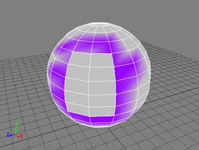
Exclude: painting affects the entire object, except for the selected polygons.
The color paint modes specify what will be painted on your object's CAV properties when you use the Paint Vertex Color tool.
From the Vertex Color tab, set the Color Paint Mode to one of the following:
RGB: painting on the object affects only the RGB channels.
You can pick a color using any of the palette controls in the Brush Properties property editor. If you set the color value using the RGBA sliders, the alpha value has no effect in this mode.
Alpha: painting on the object affects only the alpha channel.
You can set an alpha value using the A slider in the palette controls' RGBA sliders. Other color selection controls have no effect.
RGB+Alpha: painting on the object affects both the RGB and alpha channels.
You can pick a color using any of the palette controls in the Brush Properties property editor. To set the alpha value, you must use the A slider in the palette controls' RGBA sliders.
Because the 3D views do not display the alpha channel by default, you need to switch it on to see a painted alpha.
You can do this by opening the Camera Display property editor by clicking the  in the viewport (in which you are painting) and choosing Properties. Set the Vertex Color Property Display to Show Alpha.
Luminance: painting on the object affects its luminance.
When luminance mode is active, the palette controls disappear. You can set the level of luminance you are painting with by adjusting the Opacity value.
Color Correction: painting on the object modifies the current vertex colors according to the Color Correction settings.
The color correction settings replace the palette controls when color correction mode is active. They allow you to color correct by setting Hue, Luminance and Saturation shifts.
Smooth: painting on the object smooths the transition between colors on adjacent vertices. This only woks when the Color Paint Method is set to Brush.
Smoothing tends to favor the color of the vertex closest to the center of the brush stamp.
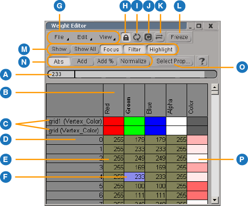
You can edit vertex colors numerically using the weight editor. The weight editor can be used for both weight maps and vertex colors as well as envelope weights.
 Animation Weight Editor or press Ctrl+E.
 Except where otherwise noted, this work is licensed under a Creative Commons Attribution-NonCommercial-ShareAlike 3.0 Unported License