Adjusts a bone's length, axis alignment, display type and size, including shadow icons. This property editor applies to bones created by any of these commands:
Choosing Create  Skeleton Draw 2D/3D Chain on the Animate or Model toolbar.
Choosing Create Skeleton Draw Bones on the Animate or Model toolbar.
To display: Select a chain bone or implicit bone and press Enter.
For information about bones/chains in general, see Skeletons.
For more information, see Changing the Shape and Size of Chain Elements.
| Icon |
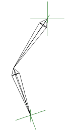
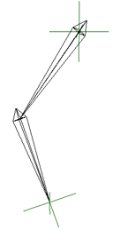
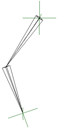
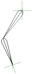
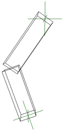
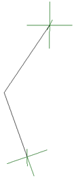
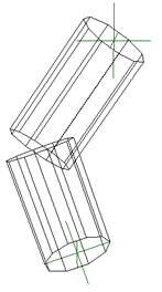
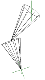
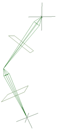
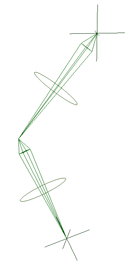
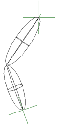
Select from a list of shapes to use for the bone's display — see Shapes for Bone Icons and Their Shadows. |
| Size |
Sets the size of the display icon for the bone on its Y and Z axes, but not its X axis (the bone's length). When you change this value, the bone's accompanying shadow always scales proportionally with it, regardless of the state of the Lock Shadow Size When Scaling option. |
| Use Display Mode |
Displays the bones using whatever the current display mode is in the viewport, such as Shaded, Constant, Wireframe, or Hidden Line Removal. This is a visual reference only — the bones are not rendered. |
A shadow is a visual reference that makes it easier to see and select chain elements. When you select a shadow, its chain element is also selected.
For more information, see Changing the Chain Element Display.
| Icon |
Select from a list of shapes to use for the bone's shadow — see Shapes for Bone Icons and Their Shadows. Select an option other than None to see the following parameters. |
| Use Display Mode |
Displays the shadow bones using whatever the current display mode is in the viewport, such as Shaded, Constant, Wireframe, or Hidden Line Removal. This is a visual reference only — the bones are not rendered. |
| Color |
Sets the color of the shadow. Select the Custom option to set a custom color using the color sliders. The resulting color appears in the color chip. You cannot change the color of the shadow if Wireframe is selected: the standard display color is used. If you select Use Display Mode, the custom color is used only with the Wireframe display mode. |
| Position |
Offsets (translates) the shadow from the bone on the X/Y/Z axes. |
| Size |
Specifies the scale of the shadow. The default value of 1 means a 1:1 ratio with the bone. |
| Lock Shadow Size When Scaling |
Keeps the shadow at a constant size when the bone is scaled in Y or Z (using the Scale transform commands, not the Size parameter above). |
Select from any of these shapes for bones and their shadows from the Icon list in their property editor.
 Except where otherwise noted, this work is licensed under a Creative Commons Attribution-NonCommercial-ShareAlike 3.0 Unported License