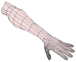
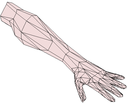
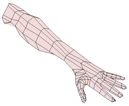
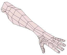
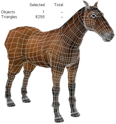
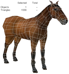
Polygon reduction lightens a heavy object by reducing the number of polygons, while still retaining a useful fidelity to the shape of the original high-resolution version. For example, you can use polygon reduction to meet maximum polygon counts for game content, or to reduce file size and rendering times by simplifying background objects.
Polygon reduction also allows you to generate several versions of an object at different levels of detail (LODs).
Polygon reduction works by collapsing edges into points. Edges are chosen according to their "energy", which is a metric based on their length, orientation, and other criteria. In addition, you have options to control the extent to which certain features, such as quad polygons, are preserved by the process.

|
|
Select one or more polygon mesh objects, polygon clusters, or polygons.
Choose Modify  Poly. Mesh Polygon Reduction from the Model toolbar.
The polygons are reduced using the default settings and the Polygon Reduction Op property editor opens. For information about adjusting the settings, see the sections that follow.
The options in the Reduction Amount box of the Polygon Reduction Op property editor specify the amount of reduction. You can specify either a percentage (ratio) or a final number of vertices or triangles. The reduction amount is animatable, so, for example, you can use an expression to control it based on the distance from the camera.
In all cases, these values are targets — the operator may not be able to achieve the exact amount of reduction for various reasons. For example, if the original object has an odd number of polygons, then it is impossible to achieve a reduction of exactly 50%.
In addition, you have the option of using a parameter map. For example, you can use a weight map and paint weights to differentiate between areas where you want more or less reduction to take place.
For more information about animated topology operators, see Special Considerations for Topology Modifications.
On the General tab of the Polygon Reduction Op property editor, set Unit to the desired value:
Ratio allows you to set the amount of reduction as a percentage of the original polygon count using the Ratio slider.
Final vertex count lets you set the number of vertices in the result using the Vtx Count slider.
Final triangle count lets you set the number of triangles (polygons after tessellation) in the result using the Tri Count slider.
Use the corresponding slider to set a target for the amount of reduction.
Before you apply polygon reduction, create a weight map or other type of parameter map as described in Parameter Maps.
The cluster that contains the map must exist before you apply the Polygon Reduction operator. If you have already applied polygon reduction, then you must disable the operator before creating the map. This ensures that the cluster containing the map is created at a lower position in the construction history than the reduction operator.
Similarly if you want to add or remove points from the cluster or paint additional weight strokes, make sure you disable the Polygon Reduction operator first.
For more information about disabling and re-enabling operators in the stack, see Disabling the Top of the Stack.
Apply polygon reduction, or re-enable the Polygon Reduction operator if you disabled it.
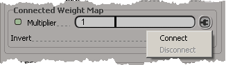
On the General tab of the Polygon Reduction Op property editor, right-click on the connection icon to right of the Multiplier slider and choose Connect.
In the pop-up explorer that appears, expand the appropriate cluster and then select the desired parameter map.
If Invert is on, areas in which the map has a low opacity are more likely to be reduced than areas with a high opacity. Areas with a weight of 1 are reduced last — they are essentially protected from reduction unless the reduction amount is so high that the other areas of the weight map cannot be reduced further.
If you want to reverse the effect of the map so that areas of low opacity are protected and areas of high opacity are reduced, turn Invert off.
If you want to paint additional strokes on a weight map after it is connected, make sure you disable the Polygon Reduction operator first.
See Parameter Maps for information about working with parameter maps in general.
If desired, adjust the Multiplier slider to modulate how strongly the values in the weight map affect the likelihood of edges collapsing.
The Smooth Transitions option is available on both the General tab and the LOD Controls tab of the Polygon Reduction Op property editor. When it is on, edges shrink before they collapse as the reduction amount is increased. In addition, corresponding properties, such as texture UVs and vertex colors, are interpolated. This allows the object to gradually morph when the reduction amount is animated, and avoids sudden popping in the object's shape or textures as edges collapse.
It is particularly useful when combined with Reduce parallel edge loops (see Preserving Quads) or LODs (see Generating LODs).
A couple of options on the General tab of the Polygon Reduction Op property editor allow you to control how reduction affects the details and shape of an object:
Sharpness controls the balance between preserving small, sharp details versus larger shapes. At low values, details that are small relative to the general shape of the object are more likely to be collapsed. At high values, they are more likely to be kept.
When you reduce an object, it usually shrinks. Preserve volume rearranges vertices to keep the object's volume unchanged. When an edge is collapsed into a point, the difference in the dihedral volume is calculated and the point is moved along its normal to compensate. In some cases, this can help maintain an object's silhouette and prevent protuberances like fingers and limbs from disappearing. However, it can also distort an object's shape, especially at high reduction amounts, so use the slider to achieve a good balance.
|
|
|
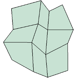
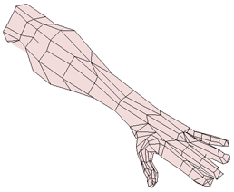
| Without Preserve volume, reduced objects will shrink. |
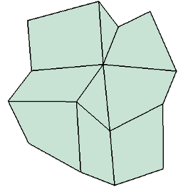
A moderate value preserves the object's silhouette. |
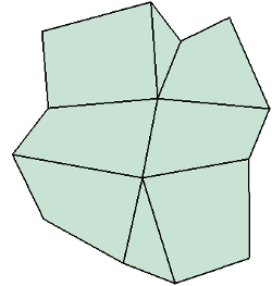
Setting the value too high introduces distortions. |
Because Preserve volume moves points, the lengths of edges are changed and this affects the order in which subsequent edges are collapsed.
When edges are collapsed on quadrilateral polygons, triangles are created. A couple of mutually exclusive options on the General tab of the Polygon Reduction Op property editor give you two different ways to make sure that the final result still contains as many quads as possible.
Reduce parallel edge loops will never create new non-quads, but it might distort certain objects depending on their geometry. Preserve quad lines has a slider so you can adjust it to minimize distortions, but at the cost of more non-quads in the result. You should try different settings to see what combination gives the best results in specific cases.
Reduce parallel edge loops collapses an entire loop of parallel edges together instead of collapsing individual edges one at a time.
Although Reduce parallel edge loops is incompatible with Enforce symmetry, it tends to preserve symmetry on truly symmetric objects anyway.
Preserve quad lines provides relative control over the amount of quads remaining in the result. After the edge with the lowest energy is collapsed, edges that were parallel to it become temporarily more likely to be collapsed next (as if their energy has been lowered).
Use the slider to control the strength of the effect: the higher the value, the more quads in the final result. A value of 0 is equivalent to turning this option off.
There are two ways to preserve symmetry during the polygon reduction process: using a symmetry map or not.
If you don't use a symmetry map, the reduction operator uses its own internal method for determining which edges are symmetric. This allows it to find local symmetries, such as between the two sides of the same finger, in addition to global symmetries such as between the fingers of opposite hands.
However, if an object has multiple planes of symmetry (like a sphere), the internal method will arbitrarily pick one pair out of many possible symmetric edges. In such cases, it may be preferable to use a symmetry map.
If you connect a symmetry map, the operator uses the map to determine which edges are symmetric. This is useful when the object is not in its base symmetric shape. It also resolves ambiguities when there are multiple planes of symmetry, and ensures that symmetrical edges are always found in spite of possible numerical imprecisions in calculations.
The symmetry map must already exist before you apply polygon reduction.
In either case, after the operator collapses an edge, it automatically collapses the symmetric edges before proceeding to the edge with the next lowest energy.
On the General tab of the Polygon Reduction op property editor, make sure that Enforce symmetry is on.
As long as you don't connect a symmetry map, the reduction operator uses its own internal method for determining which edges are symmetric.
If desired, you can adjust Tolerance level. The tolerance is the maximum difference in energy between symmetric edges. If a symmetric edge has an energy difference greater than the tolerance, it is not collapsed automatically (although it may still be collapsed later in the process, depending on its own energy).
Before you apply polygon reduction, create a symmetry map by selecting the object and choosing Get Property Symmetry Map from any toolbar.
The symmetry map must exist before you apply the Polygon Reduction operator. If you have already applied polygon reduction, then you must disable the operator before creating the symmetry map. This ensures that the symmetry map is created at a lower position in the construction history than the reduction operator.
For more information about disabling and re-enabling operators in the stack, see Disabling the Top of the Stack. For more information about symmetry maps, see Applying Symmetry Maps.
Right-click on the Use symmetry map connection icon and choose Connect.
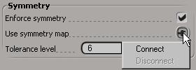
In the pop-up explorer that opens, expand the appropriate cluster and select the desired symmetry map. The connection icon appears red to show that a map is connected.
If you change your mind and want to disconnect the symmetry map or connect a different one, right-click on the Use symmetry map connection icon again. The connection icon appears gray when no map is connected.
The Feature Preservation tab of the Polygon Reduction Op property editor includes several options that help to preserve specific features during the reduction process.
Use the Preserve sliders to control the priority given to preserving edges that meet the corresponding criteria:
Input cluster boundaries are the boundaries of the polygons or polygon clusters on which you applied reduction (if you did not apply it on an entire object).
Hard edges are edges that have been marked as hard using Modify Component Mark Hard Edge/Vertex.
Creases are edges that have had crease values set using Modify Component Set Edge/Vertex Crease Value.
Material boundaries are the boundaries of polygon clusters with local materials.
Property discontinuities are breaks in the texture UVs, user normals, or vertex color (CAV) properties. User data is not considered.
Setting a slider to its maximum value preserves the corresponding edges completely, and may prevent the operator from reaching the amount of reduction set on the General tab. Setting a value of 0 means that the criterion is not considered at all when reducing polygons. Turning a checkbox off is equivalent to setting a value of 0.
Before you apply polygon reduction, create a cluster containing the points you want to preserve.
The cluster must exist before you apply the Polygon Reduction operator. If you have already applied polygon reduction, then you must disable the operator before creating the cluster. This ensures that the cluster is created at a lower position in the construction history than the reduction operator.
Similarly if you want to add or remove points from the cluster, make sure you disable the Polygon Reduction operator first.
For more information about disabling and re-enabling operators in the stack, see Disabling the Top of the Stack.
Apply polygon reduction, or re-enable the Polygon Reduction operator if you disabled it.
On the Feature Preservation tab of the Polygon Reduction Op property editor, right-click on the Connected vertex cluster connection icon and choose Connect.
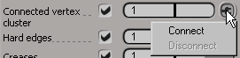
In the pop-up explorer that opens, select the desired cluster. The connection icon appears red to show that a cluster is connected.
Use the Connected vertex cluster slider to set the priority for preserving the vertices in the connected cluster.
As with the other properties, setting the slider to its maximum value preserves the corresponding edges completely, and may prevent the operator from reaching the amount of reduction set on the General tab. Setting a value of 0 means that the connected vertices are not considered at all when reducing polygons. Turning the checkbox off is equivalent to setting a value of 0.
If you change your mind and want to disconnect the cluster or connect a different cluster, right-click on the Connected vertex cluster connection icon again. The connection icon appears gray when no cluster is connected.
Use the Optimize for attributes sliders to bias the reduction process by taking into account value differences in other properties such as texture UVs, vertex colors (CAVs), weight maps, and user normals. A value of 0 ignores the attribute when considering an edge for reduction, while non-zero values set a weighted priority which is considered together with the edge's geometric energy.
Normally when an edge is collapsed, the new vertex is created at the midpoint of the edge. However, if Use existing vertex positions (available on the Feature Preservation tab of the Smooth property editor) is active, then edges collapse to one of the two endpoints. This means that each point in the reduced object shares its position with a point in the unreduced object. This could be useful in some situations, for example, if you are exporting several versions of the geometry for use with an engine that does not interpolate attributes.
If you are using this option, you probably also want to set Preserve volume to 0 on the General tab of the Smooth property editor; otherwise, points will be moved after edges are collapsed and the positions will no longer correspond.
You should also be aware that Use existing vertex positions may break symmetry if edges cross the plane of symmetry.
The LOD Controls tab of the Polygon Reduction Op property editor allows you to generate several versions of an object at different levels of detail. The operator precalculates the geometry for each version and caches the results. This has several advantages:
It avoids potentially expensive recomputations when the amount of reduction is animated.
You can transition smoothly between discrete LODs, and avoid texture popping and other artifacts that might occur when edges are collapsed individually.
You can pregenerate several LODs of the same object for use as game content or for any other purpose.
On the LOD Controls tab of the Polygon Reduction Op property editor, turn Use LODs on.
Adjust the Settings to control the amount of reduction:
Reduction ratio per LOD is the percentage of reduction applied successively at each LOD. For example, if this value is 50, the first LOD has a reduction of 50%, the second LOD has a total reduction of 75% (half of the remaining polygons), the third LOD has a total reduction of 87.5%, and so on.
Max ratio is a clamp that sets the maximum total amount of reduction. This overrides the amount of reduction set on the General tab, and prevents the object from becoming too distorted at high reduction amounts.
There are two ways to control which LOD is currently in use:
If Control by LOD Stage - Activate is off, adjust the Reduction Amount on the General tab of the Polygon Reduction Op node. The LOD which is closest to the amount of reduction is used. If Smooth transitions is on, reduction amounts that fall between discrete LODs morph between the levels.
If Control by LOD Stage - Activate is on, specify the LOD directly using LOD Stage. This is especially useful if you want to export LODs for game content or other purposes.
Activate LODs, and make sure that Control by LOD Stage - Activate is off.
If desired, turn on Smooth transitions on either the General or LOD Controls tab of the Polygon Reduction Op property editor:
When it is on, the object morphs smoothly between LODs as the reduction amount varies between levels.
When it is off, the geometry abruptly snaps to the closest LOD as the reduction amount changes.
You can also restrict the interval during which the morphing occurs to a fraction of the interval between LODs using Transition size.
Activate LODs, and make sure that Control by LOD Stage - Activate is on.
Adjust LOD Stage to specify the LOD. The meaning of the stages depends on whether Smooth transitions is on or off.
| Control by LOD Stage, with Smooth transitions = off |
||
|

|
|
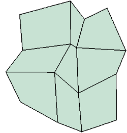
| Stage 0 Unreduced geometry. |
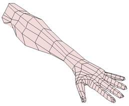
Stage 1 Reduced geometry. |
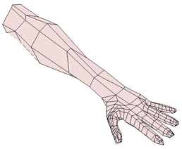
Stage 2 Further reduced geometry. |
1 is the unreduced object morphed to first level of reduction. Edges have been shrunk to zero length but coincident points have not been merged. It has the same number of vertices as level 0.
2 is the first level of reduction, after coincident points have been merged.
3 is the first level of reduction morphed to the second level of reduction, and so on.
 Except where otherwise noted, this work is licensed under a Creative Commons Attribution-NonCommercial-ShareAlike 3.0 Unported License