You can convert curves to create complex polygon meshes with holes. The Curve to Mesh Converter is also used to create planar and solid mesh text.
For information about creating text curves, see Creating Text.
For information about controlling how text and other curves are converted to polygon meshes, including extruding and beveling, read on.
If you understand how the conversion treats the input curves, you'll know what to expect in the resulting polygon mesh.
You can use multiple curve objects, curve objects with multiple subcurves, or a combination.
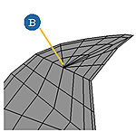
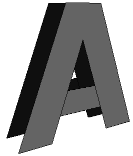
You should have at least one closed exterior curve. Multiple closed exterior curves become disjoint parts of the same mesh object.
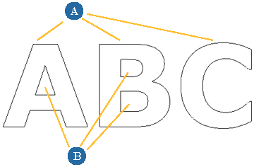
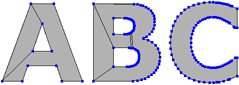
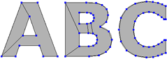
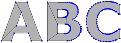
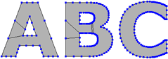
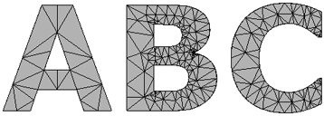
Exterior closed curves become disjoint parts of the same mesh object (A). Interior closed curves can become holes (B).
You can use open, interior curves to define contour (or "flow") lines inside the mesh.
Closed interior curves can be used either to define holes or as interior contours for the tesselation.
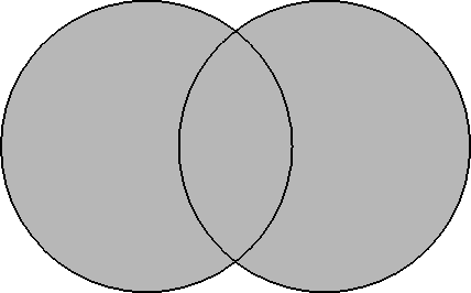
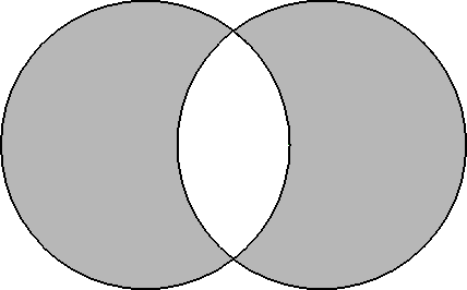
Curves can intersect or self-intersect. These intersections can be used to define holes or not, depending on the options you choose.
Instead of using a single closed curve to define the exterior contour, you can use multiple curve objects that enclose an area.
In this case, Curve Can Intersect must be on — see Setting General Options.
Curves can be non-planar. However, for the purpose of tessellation, the curves are projected onto their average plane and then after the tessellation, depth is added to the resulting mesh based on the height of the original curves.
If the curves are extremely skewed or twisted, they may intersect when projected and the resulting tessellation may not be what you expected — it's easier to visualize the results if the curves are almost coplanar.
Whenever you generate a new object from other input objects, you can manage the inputs, for example, hide or delete them. See Managing Generator Inputs.
You can also set Update with input transforms. This recalculates the mesh when the input curves are transformed. Leaving this option off prevents potentially long computations when the curves are moved.
The items in the Step and Options sections of the General tab of the Curve to Mesh Converter property editor control how the input curves are treated.
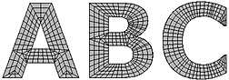
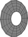
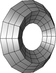
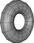
The Step options control how many vertices are created for every knot in the input curves. You can control the values for the exterior Contours and the interior Holes separately (unless Curves Can Intersect is on).
The actually number of vertices in the final geometry can also be affected by Filter Colinear Curves. In the illustrations above, that option is on.
The Create Holes option determine whether closed interior curves and intersections result in holes. You can turn this option off to use closed interior curves as interior edges for the tessellation; this lets you control the tessellation more directly to meet your final needs, especially if you are using non-planar curves to create a terrain-like effect.
This option is recursive; it will create holes within polygon "islands" within other holes, and so on.
The Filter Colinear/Spike Points option can be used to remove points from straight edges to simplify the geometry, as well as to eliminate spiky noise in the input curves. Turn this option on to reduce the geometry. Turn it off if you need the number and distribution of vertices in the polygon mesh to reflect the actual vertices in the input curves, or if you need the extra geometry, for example, to allow the polygon mesh to deform smoothly.
Use Min. Angle Colinear to specify which vertices are considered colinear. Any vertex with two edges that meet at an angle greater than this value in degrees is removed.
Similarly, use Max Angle Spike to specify which vertices are considered spikes. Any vertex with two edges that meet at an angle less than this value in degrees is removed. This applies to both convexities and concavities.
The Curves Can Intersect option allows holes to be created in areas bounded by the intersection of two curves. This option may be necessary to provide the correct tessellation on some imported EPS curves. It treats all input curves as if they were one object, so if you turn this on then you cannot create partition clusters as described in Creating Clusters.
In addition when this is on, you cannot set the Step value for Holes, nor can you use Proportionally Smaller for Holes on the Bevel tab. If this option is off and the curves do intersect, you might not get the desired results.
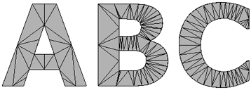
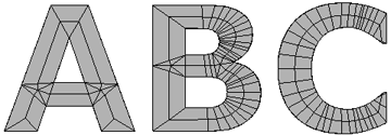
Tessellation is the process of tiling the curves' shapes with polygons. Softimage offers three different tessellation methods:
Minimum Polygon Count uses the least number of polygons possible.
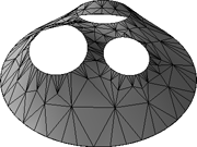
Delaunay generates a mesh composed entirely of triangular polygons. This method gives consistent and predictable results, and in particular, it will not give different results if the curves are rotated.
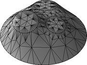
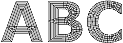
Medial Axis creates concentric contour lines along the medial axes (averages between the input boundary curves), morphing from one boundary shape to the next. This method creates mainly quads with some triangles, so it is well-suited for subdivision surfaces.
Each method has its own set of options, described in the sections that follow.
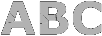
The Minimum Polygon Count tessellation method uses the least number of polygons possible. For a single contour curve with no holes, this results in exactly one polygon. When holes are present, there are multiple polygons and their shapes are not predictable.
This is because of the fundamental rules for valid polygon meshes in Softimage: points cannot be used more than once in a the same polygon and the edges of a polygon must all be connected — you cannot have a hole in a single polygon because the outer and inner boundaries would be disjointed.
In general, Minimum Polygon Count creates irregularly shaped n-sided polygons. For this reason, it is best used when you need to keep the geometry light on simple objects that will not be deformed. Of course, you can always add and remove edges manually.
The Delaunay tessellation method (or more precisely, constrained Delaunay tessellation) generates a mesh composed entirely of triangular polygons. This method gives consistent and predictable results, and in particular, it does not give different results if the curves are rotated.
With this method, there are several options for fine-tuning the tessellation further.
Turn Enable on and then adjust the Added Vertices Limit slider.
This limits the total number of new vertices that can be added by the Minimum Angle and Maximum Area options.
Use this option as a precaution against accidentally setting the other options to values that would create huge amounts of geometry with long processing times.
It is not recommended that you rely on this option to control the final number of vertices because it can force the tessellation to stop before the process is completed, thereby giving an unpredictable combination of polygon shapes and sizes. Look at the Stats in the property editor to see whether your object is at or near the limit.
Set Boundary Split to one of these options:
Free: Allows the boundary edges along the outer contour and inner holes to be split further during tessellation.
This is particularly useful for text and other shapes that may contain straight edges that need to be deformed smoothly.
None on Contour Only: Allows boundary edges along inner holes to be split, but not boundary edges along the outer contour.
Note that this may affect the uniformity of the mesh if you are using Minimum Angle or Maximum Area.
None (Contour and Holes): Does not allow any boundary to be split.
Again, this may affect the uniformity of the mesh if you are using Minimum Angle or Maximum Area.
The Medial Axis tessellation method creates concentric contour lines along the medial axes (averages between the input boundary curves), morphing from one boundary shape to the next. This method creates mainly quads with some triangles, so it is well-suited for subdivision surfaces.
With this method, there are several options for fine-tuning the tessellation further.
Turn on Split edges to enhance.
This option adds vertices to allow the contour lines to follow the medial axes more accurately.
You should turn this option off if you are not creating holes (that is, if Create Holes is off on the General tab); otherwise, there may be shading artifacts along internal curves.
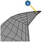
When this value is 0, the medial axis intersects boundaries at each point of concavity, which can often create many small triangles especially in sharp extremities.
When this value is positive, the medial axis does not extend completely to the boundary and the remaining area is tessellated with a fan shape.
When this value is negative, it creates sharper embossing effects.
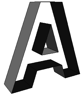
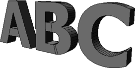
You can extrude the tessellated mesh to add depth using the controls on the Extrude tab of the Curve to Mesh Converter property editor.
The only difference between the Create  Text Planar Mesh and Create Text Solid Mesh is the default value of Extrude Length.
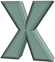
When converting curves to polygon meshes, beveling extends the contours using a profile.
The Bevel options on the Bevel tab of the Curve to Mesh Converter property editor control the size of the bevel:
Depth controls how much the bevel protrudes in front and in back of the base mesh.
The bevel profile is automatically scaled so that the width of its bounding box equals this value. This value is in addition to any extrusion set on the Extrude tab.
Height is a scale factor that modifies the profile curve in the direction orthogonal to the Depth. Positive values push the sides out, while negative values push the sides in.
If your curves have small, thin features and sharp, closely-spaced corners, then don't set this value too high.
Proportionally Smaller for Holes in the Options box further scales the bevel profile applied to holes.
This is useful to avoid overlapping geometry when holes are small compared to the bevel size. This option is not available when Curves Can Intersect is on in the General tab.
Interior controls the direction of the bevel.
When this option is on, the front and back are beveled outward. As a result, the silhouette matches the original curves but polygons may intersect or interpenetrate in narrow areas when the bevel depth is high.
When this option is off, the sides of the tube are extruded outward. In some cases, this may distort the object's outline or cause separate islands of polygons (such as characters in text) to collide with each other.
The options in the Sides box allow you to bevel the Front or Back individually.
Mitering creates sharp corners, like at the corners of a picture frame.
Min Miter Angle sets the threshold for mitering. Adjacent polygons whose dihedral angle is greater than this value are mitered.
For best results, set this to the same value as the Discontinuity Angle in the object's Geometry Approximation property — this ensures that the discontinuous angles of the bevel are aligned with the discontinuous edges of the extrusion and avoids shading artifacts.
For more information about Geometry Approximation in general, see Applying and Editing Geometry Approximation.
Mitering can sometimes produce ugly results with extremely sharp angles. In these situations, you can round the corners instead.
Use the Convex and Concave sliders in the Corner Mitering box to define the minimum threshold for mitering convex and concave angles in degrees. Angles that are sharper than these values are rounded. A value of 0 is equivalent to turning rounding off.
Use Roundness Subdivisions to control the smoothness of the rounding. Higher values produce smoother arcs with denser geometry. A value of 0 creates a flattened effect like a sawn-off corner.
You can choose one of several preset profile curves or draw your own.
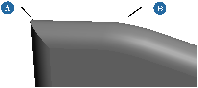
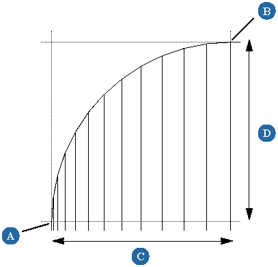
In the Front view, draw an open profile curve. The direction in which you draw the curve affects the direction of the bevel.
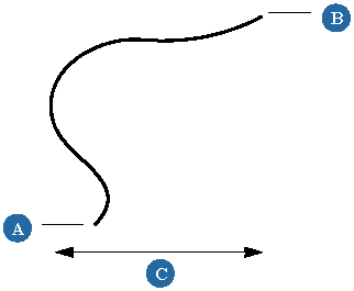
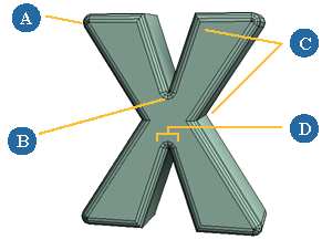
Front view of custom profile curve: the curve starts at (A) and ends at (B). Depth is based on the width of the bounding box (C).
Click the connection icon (the little plug on the far right of the Curve box on the Bevel tab of the Curve to Mesh Converter property editor) and choose Pick and Connect.

Pick the profile curve. The curve is connected as an input and the connection icon changes.
A modeling relation exists between the beveled polygon mesh and the custom profile curve. Modifying the profile curve automatically changes the bevel shape.
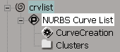
In an explorer, click the curve's NURBS Curve List icon. An empty property editor opens.
Choose a file name and path for the preset.
It is recommended that you save it in the Data\DSPresets\2DCurves folder of your user or workgroup application data path — you can use the Paths button to quickly switch to those locations.
When you convert a set of curves to polygon mesh, you can create polygon clusters automatically.
You can automatically create polygon clusters based on separate characters when converting text, or based on the disconnected
islands created by separate outer contour curves when converting curves. This makes it easier, for example, to break up the
mesh by selecting clusters and extracting new polygon mesh objects using Create Poly. Mesh Extract from Polygons.
If you change the resulting polygon mesh structure by adding, removing, or moving curves after creating island/character clusters, the clusters are not updated automatically. If the number of polygon islands is different, then you must re-create the clusters again.
Note also that you cannot create island/character clusters if Curves Can Intersect is on.
You can automatically create five polygon clusters corresponding to the Front, FrontBevel, Extrusion, BackBevel, and Back. This is useful, for example, if you want to apply different materials to those sections.
These clusters are automatically updated even if you change the mesh structure by changing settings, for example, setting a bevel after clicking this button.
The clusters are created even if they are empty. For example, if you do not apply a bevel then FrontBevel and BackBevel contain no polygons.
The clusters span multiple characters or islands. If you explode the mesh after creating these clusters, each mesh object in the exploded hierarchy will have these five clusters.
When converting curves to polygon meshes, you can create a hierarchy of separate polygon mesh objects. There is one new object for each "island" of polygons (or for each character, if using text) and all objects are parented under a common null.
Choose Explode Mesh on the General tab of the Curve to Mesh Converter property editor.
Each island of polygons (or character) is automatically extracted and parented under a new null object. The null object is selected in branch mode.
A modeling relation exists between the unexploded mesh and the extracted objects, so modifying the options on the Curve to Mesh Converter property editor affects the extracted objects as well.
However if you change the number of polygon islands, for example, by adding or removing input curves after exploding, you should re-explode the mesh.
 Except where otherwise noted, this work is licensed under a Creative Commons Attribution-NonCommercial-ShareAlike 3.0 Unported License