You can constrain objects between two, three, or any number of points (object centers).
You can position an object to be constrained between two other objects. By default, the constrained object's X axis is oriented along the vector that goes from the first-selected constraint to the second one. You can, however, select the object to be constrained by its Y or Z axis.
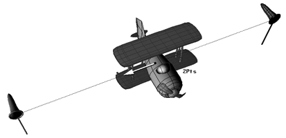
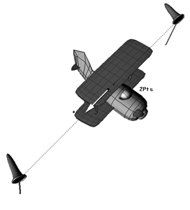
A plane is constrained midway between two points (windsocks) When the windsocks are repositioned, the plane's position is updated as well.
This constraint is useful for keeping an object between two points pointing along their direction, such as a muscle between two arm joints.
It also provides an easy way to convert two positions into an orientation for motion capture. When you have motion curve data without orientation information, you can infer rotations from position data by using this constraint.
Choose Constrain  2 Points and pick the two constraining objects.
The order in which you select your constraining objects is important to get the correct orientation of the constrained object.
In the Two Points constraint property editor, you can set the Distance Percentage, which is the relative distance of the constrained object between its constraining objects.
A value of 50 (default) positions the constrained object centrally between the two constraining objects. A value of less than 50 positions the constrained object closer to the first constraining object; and a value of more than 50 positions the constrained object closer to the second constraining object.
You can set position offsets on any axis of the constrained object using the X, Y, Z sliders in the property editor. See Creating Offsets between Constrained and Constraining Objects for more information.
You can set tangency (see Tangency Constraints) and up vector direction (see Up-vector Constraints) constraints for the constrained object. By default its X axis is repositioned in the direction of the second constraining object's center.
When you move the constraining objects (one or both), the constrained object readjusts to keep between them.
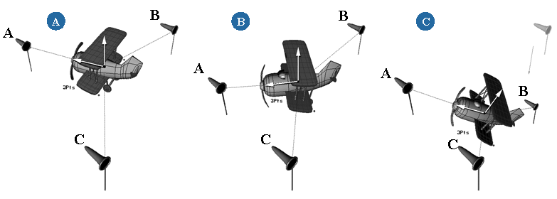
You can position an object to be constrained within three constraining objects or nulls in a type of invisible triangle. By default, this orients the constrained object's Y axis to the normal of the plane that is defined by the three constraining objects. Its X axis is constrained toward the center of the first constraint object you pick.
This constraint is useful for converting three positions from motion capture data into an orientation. When you have motion curve data for positions only, such as three points on the hips and trunk of an actor, you can infer the rotation of its body by using this constraint.
Choose Constrain 3 Points and pick the three constraining objects.
The order in which you select your constraining objects is important so you can get the correct orientation for the constrained object. By default, the first constraint defines the X axis and the two remaining constraints together define the orientation of the plane for the Y and Z axis.
In the Three Points constraint property editor, you can set the U/V/W %age, which is the U, V, and W coordinates to set the relative distance of the constrained object between its constraining objects.
A value of 33.33 for each coordinate (the default) positions the constrained object centrally between the three constraining objects.
A U value of more than 33.33 positions the constrained object closer to the first constraining object; a V value of more than 33.33 positions the constrained object closer to the second constraining object; and a W value of more than 33.33 positions the constrained object closer to the third constraining object.
You can set position offsets on any axis of the constrained object using the X, Y, Z sliders in the property editor. See Creating Offsets between Constrained and Constraining Objects for more information.
You can set tangency (see Tangency Constraints) and up vector direction (see Up-vector Constraints) constraints for the constrained object. By default, its X axis is repositioned in the direction of the first constraining object's center, and its Y axis is oriented to be perpendicular to the plane formed by the three constraining objects.
When you move any of the constraining objects, the constrained object readjusts to keep properly positioned and oriented within its confines.
You can position an object to be constrained centrally within multiple constraining objects or nulls. This constraint calculates the average position of all the points and applies the resulting value as a constraint (a single "pivot" point).
 Except where otherwise noted, this work is licensed under a Creative Commons Attribution-NonCommercial-ShareAlike 3.0 Unported License


