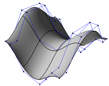
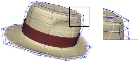
Surfaces are one of the basic types of renderable geometry in Softimage. Surfaces can model precise shapes using less geometry than polygon meshes and they're ideal for smooth, manufactured objects like car and aeroplane bodies.

NURBS surfaces allow for smooth geometry with relatively few control points.
In Softimage, surfaces are NURBS patches. Mathematically, they are an interconnected patchwork of smaller surfaces defined by intersecting NURBS curves.
Surfaces are also the building blocks of surface meshes, which are described in Surface Meshes.
Surfaces have many components and attributes. The types of surface components are described here. To select components on surfaces and other objects, see Selecting [Scene Elements], in particular Overview of Selection and Selecting Components. To display surface components and other data, see Displaying Types of Elements and Other Data [Basics].
The U and V rows stop at the boundaries between subsurfaces on assembled surface meshes.
Points are the control points of the curves that define the surface.

You cannot add or remove points directly, but you can add and remove knots as described in Adding Knot Curves and Removing Knot Curves — this has the effect of adding or removing points indirectly.
NURBS hulls (called simply lines in previous versions of Softimage 3D software) are display lines that join consecutive control points. It can be useful to display them when working with curves and surfaces.
Surface knots are the knots of the curves that define the surface; they lie on the surface where the U and V curve segments meet. Knot curves (sometimes called isoparams or isoparms) are sets of connected knots along U or V — they are the "wires" shown in wireframe views. You can select knot curves and use them, for example, to build other surfaces using the Loft operator. You can add and remove knots as described in Adding Knot Curves and Removing Knot Curves.

The minimum and maximum U and V values define the boundaries of a surface. On surfaces that are open in one or both directions, these are the outer edges. You can use the Boundaries selection filter to help you pick boundaries for lofting and other operations.
When working with surfaces, it may be helpful to display NURBS boundaries. This shows the U = 0 boundary in red and the V = 0 boundary in green. This display option is sometimes also called boundary flags or edge flags.
Isolines are not true components. They are, in fact, arbitrary lines of constant U or V on a surface. You can use the U and V Isoline selection filter to help you pick isolines for lofting and other operations.

Surface curves and trim curves are components that result when you project a curve object onto a surface. For more information, see Projecting and Trimming with Curves.
Samples are used to adjust textures on objects. You can select them in the 3D views and manipulate them in the texture editor. For more information, see Working with UVs in the Texture Editor [Texturing].
Subsurfaces are the individual NURBS surfaces that are components of assembled surface meshes. For more information, see Surface Meshes.
 Except where otherwise noted, this work is licensed under a Creative Commons Attribution-NonCommercial-ShareAlike 3.0 Unported License