You can use the SDK Operator Wizard to generate the code for a self-installing plug-in that contains a custom operator. In addition to generating the skeleton code for the plug-in and the operator, the wizard can also generate the code required to add the command to apply the operator.
The SDK Operator Wizard can generate enough code to establish a operator with valid connections and even the command to apply it; however, you still need to provide the code to calculate the scene change. The wizard does not generate more than the basic shell for the Update callback, which is where the algorithm for the operator is implemented.
To create a custom operator using the SDK Operator Wizard
Click File Plug-ins to open the Plug-in Manager.
In the Tools Development Environment layout, you can click the Plug-ins tab to switch to the Plug-in Manager view.
In the Operator Name box, type a name for the operator.
The first character in an operator name should be a letter. Subsequent characters can be letters, numbers, or underscore (_) characters.
By default, the plug-in name is based on the operator name. If you want to change the plug-in name, type a different name in the Plug-in Name box.
Note that if you change the operator name later, the wizard overwrites your plug-in name with a default generated name.
In the Language list, click the language you want to generate.
Click the Connections tab, and then specify the output and input connection ports.
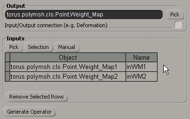
The wizard makes it easy for you to set up your connections through the UI and then modify them to suit your needs after the code is generated. For example, if you wanted to create a weight map generator operator by blending two other weight maps:
Pick the two weight maps to be blended as input. You can also specify a variable Name to use for your input ports in the Update function.
The wizard will generate code that looks something like the following snippet. Notice that these connections we set up on the Connection tab actually appear in the callback for the command to apply the operator, and in the operator's Update callback.
function ApplyMyWtMapOp_Execute(  )
{

	// ...
	var newOp = XSIFactory.CreateObject("MyWtMapOp");
	newOp.AddOutputPort("torus.polymsh.cls.Point.Weight_Map");
	newOp.AddInputPort("torus.polymsh.cls.Point.Weight_Map1");
	newOp.AddInputPort("torus.polymsh.cls.Point.Weight_Map2");
	newOp.Connect();
	return newOp;
}

function MyWtMapOp_Update( ctxt )
{
	var inWM1 = ctxt.GetInputValue(0);
	var inWM2 = ctxt.GetInputValue(1);

	// ...
	output = ctxt.OutputTarget;
	return true;
}
It is recommended to make the port connections generic so that your operator can be reused in other contexts. For example, you can try to establish a connection based on what objects are selected or launch a picking session:
function ApplyMyOp_Execute(  )
{
	// ...
	var newOp = XSIFactory.CreateObject("MyOp");

	// Launch a picking session to get the connections
	var btn, outWMap;
	var collWMaps = new ActiveXObject("XSI.Collection");
	do {
		var rtn = PickObject( "Pick the weight map to write to", "Pick the weight maps to blend" );
		btn = rtn.Value("ButtonPressed");
		switch (btn) {
			case 1 :
				outWMap = rtn.Value("PickedElement");
				break;
			case 2 :
				collWMaps.Add( rtn.Value("PickedElement") );
				break;
			default :
		}
	} while (btn)

	// Extract the input weight maps from the XSICollection
	var inWMap1 = collWMaps(0);
	var inWMap2 = collWMaps(1);

	// Test what we was picked & if it's ok hook up the ports.
	if (
			outWMap.IsClassOf(siClusterPropertyID) &&
			inWMap1.IsClassOf(siClusterPropertyID) &&
			inWMap2.IsClassOf(siClusterPropertyID) )
	{
	} else {
		Application.LogMessage( "Could not connect all ports (one or more specified "
			+ "objects were invalid connections for this operator). Please try again." );
		return false;
	}

	newOp.AddOutputPort(outWMap.Kinematics.Global);
	newOp.AddInputPort(inWMap1.Kinematics.Global);
	newOp.AddInputPort(inWMap2.Kinematics.Global);
	newOp.Connect();
	return newOp;
}
For an example of converting wizard-generated code into a truly dynamic operator, see Using the Wizard to Create Dynamic Operators.
Click the Code tab. Here you can control which callbacks the wizard will generate, such as callbacks to define the command for applying the operator, and callbacks to allow you to store and clean per-instance user data.
If you want to add parameters or buttons to the operator's property page, you can define each parameter using the options in the Define Item group on the Add Parameter tab and then click AddItem at the bottom of the page to add the parameter as defined by these options to the operator's property page.
Once you have defined your parameters, click the Layout (Optional) tab to provide some layout on the property page. Here are some of the customization features available through the wizard:
The wizard can get you started with customizing the layout for your operator's property page, but there are other possibilities available by modifying the DefineLayout, such as:
For more information on the kinds of controls you can add and customize, see Interacting with the User.
When you are finished setting up all connections, code, parameters, etc., click Generate Operator to generate the custom operator.
The generated plug-in is automatically loaded and executed, and the code is loaded into the script editor.
You can turn on operator debugging in an existing plug-in. Open the plug-in in a text editor or script editor, right-click in the editing pane, point to Tools, and then click Enable Operator Debugging. Extra operator information will now be logged to history.
You can save wizard presets for types of operators that you frequently want to generate.
The wizard creates a model named SDK_Wizards, and under that model puts a custom property for each operator you create. You can open the wizard for an operator by double-clicking the corresponding custom property.
The Plug-in Info tab allows you to enter the information required to generate the XSILoadPlugin function, which registers the plug-in items such as operators and commands with Softimage.
Specifies the name of the operator. The first character should be a letter. Subsequent characters can be letters, numbers, or underscore (_) characters.
The operator name is also used to name the generated callback functions. If you change the operator name after the code is initially generated, you'll have to edit the call to PluginRegistrar.RegisterOperator or PluginRegistrar::RegisterOperator in the generated XSILoadPlugin function. Note that changing the operator name (the first argument to PluginRegistrar.RegisterOperator or PluginRegistrar::RegisterOperator) means you have to change the names of the operator callback functions (such as Update and Init).
The Connections tab allows you to define the input and output connection ports for the operator.
You can either type the name in the text box or pick it from the UI by clicking Pick beside it. If you are writing a deformer operator, you must use the same connection node for the input and output. The wizard automatically creates an input entry based on the output definition if you select the Input/Output connection option.
There are some restrictions on what you can define as an input: you need to specify specific data, such as a primitive, a parameter, a property, clusters, or either global or local kinematics. Because of this restriction, if you use the Input/Output connection option, the output must the same node. If the operator will not be a deformer, you can specify any one of those specific data types.
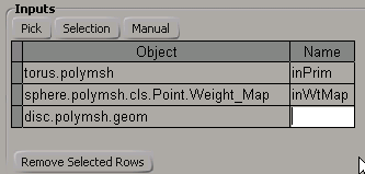
There are three ways to specify input connections:
The Inputs grid provides the full path of the node to connect to as well as a place to specify a custom Name for the connection. The Name you specify here will be used in the generated Update function as a meaningful variable name, like inPrim, inClusterProp, inParentPos, etc. If you leave the name blank, the variable names will be something like Input0, Input1, etc.
The Code tab allows you to specify what code the wizard will generate in some very specific cases.
Specifies whether to set the CustomOperator.AlwaysEvaluate or CustomOperator::PutAlwaysEvaluate property to true or false in the DefineLayout callback.
Generate Command to Apply the Operator
Specifies whether to automatically create a command to instantiate the operator and hook it up to its connections. If this option is selected, the wizard will generate Init and Execute callback functions based on the information specified on the Code tab.
Specifies whether to generate the Init callback. The code inside this callback initially just logs information messages, but you typically use it to store instance data.
Specifies whether to generate the Term callback. The code inside this callback initially just logs information messages, but you typically use it for clean up.
This section allows you to define the custom parameters for the operator. These settings tell the wizard how and what code to generate. From there you can customize it further and add extra functionality as desired. These settings basically correspond to the way the generated code calls the XSIFactory.CreateParamDef or Factory::CreateParamDef method.
Specifies the data type for the parameter (the Type argument of the XSIFactory.CreateParamDef or Factory::CreateParamDef method). Most of these types correspond to actual data types (integer, string, boolean, etc.); however, the Button option simply adds a button (it is not a type of parameter).
Depending on the value you choose, some of the following settings may not be available. For example, only parameters with a numerical data type will have the ability to set value ranges (Min, Max, etc.). For buttons, only the Name/Label and Callback settings are available.
Specifies the name for the parameter (the ScriptName argument of the XSIFactory.CreateParamDef or Factory::CreateParamDef method). By default it is also the label that will appear in the property page, but you can change the code manually if you want to use something different (specify the user-friendly string in the Name argument of the CreateParamDef).
Specifies whether users can write to the parameter. This corresponds to the siReadOnly value of the Capabilities argument (XSIFactory.CreateParamDef or Factory::CreateParamDef method).
Specifies whether the parameter can be animated. This corresponds to the siAnimatable value of the siCapabilities (the Capabilities argument XSIFactory.CreateParamDef or Factory::CreateParamDef method).
Specifies whether the wizard should generate an event callback function for the parameter or button. The callback type varies depending on the type of parameter (or whether it's a button). For example, for all parameters in an operator implemented with the C# or C++ language, the wizard will generate the OnClicked callback; for operators implemented in a scripting language, the wizard will generate an OnChanged callback for parameters and an OnClicked callback for a button.
Specifies the default value to use for the parameter (the DefaultValue argument of the XSIFactory.CreateParamDef or Factory::CreateParamDef method). This setting appears as a text box for the Text (string) type, a checkbox for the Boolean type, a slider for numeric types, and a color box for the Color type. It is not available for FCurves, Grid Controls and buttons.
Specifies the lower limit of the range of valid values for the parameter (the Min argument of the XSIFactory.CreateParamDef or Factory::CreateParamDef method). This setting is only available to parameters of numeric type.
Specifies the upper limit of the range of valid values for the parameter (the Max argument of the XSIFactory.CreateParamDef or Factory::CreateParamDef method). This setting is only available to parameters of numeric type.
Toggles availability of the UIMin and UIMax control settings which allow you to define the visible range of values for a numeric slider. This option is only available to parameters of numeric type.
Specifies the lower limit of the range of values to represent on the parameter's slider bar when the property page is displayed (the SuggestedMin argument of the XSIFactory.CreateParamDef or Factory::CreateParamDef method). This setting is only available to parameters of numeric type.
Specifies the upper limit of the range of values to represent on the parameter's slider bar when the property page is displayed (the SuggestedMax argument of the XSIFactory.CreateParamDef or Factory::CreateParamDef method). This setting is only available to parameters of numeric type.
This section allows you to arrange how the parameters appear on the operator's property page. Much of the functionality of the PPGLayout or PPGLayout object is provided here.
adding parameters to be displayed from the Parameters box
tweaking the order of appearance using the Layout button controls
adding special layout control brackets from Groupings (such as tabs, groups and rows)
assigning parameters by moving them in and out of these control brackets
This box represents the set of parameters that will appear on the operator's property page. The order in which parameters are arranged in this list (and eventually on the property page) can be controlled using the Up and Down button controls underneath the list box.
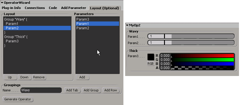
The Layout box represents Groupings as blocks delimited by labeled brackets inside which parameters can appear. The parameters that appear inside these blocks are considered to be assigned to that control. For example, given the following Layout listing, you can see that Param1 and Param2 will appear inside the Wavy group and Param3 will appear inside the Thick group:
The Remove button allows you to remove either Groupings controls or parameters from the list.
To remove a grouping control from the Layout list
Click Remove. The grouping control brackets disappear from the Layout list leaving the parameters intact. The parameters are now nested under the next highest control.
For example, if the parameters were nested inside a Row on a Tab and you remove the row, the parameters now appear directly inside the Tab.
The Parameters list displays all parameters defined for the operator. By default, all will appear on the property page until you specifically declare you want a parameter to appear in the layout by making it appear in the Layout box. However, if just one parameter appears in the Layout box, only the parameters in the Layout box will be visible on the property page.
To add a parameter to the Layout list
Click Add underneath the Parameters list.
Notice that adding parameters to the Layout list does not remove them from the Parameters list.
The wizard will generate a PPGLayout.AddItem or PPGLayout::AddItem call in the DefineLayout callback for each parameter appearing in the Layout list.
The Groupings section provides a mechanism for adding special controls like tabs, groups and rows to the property page. Each tab or group must be identified by a label which you can specify in the Name text box. Then you click the button corresponding to type of control (AddTab, AddGroup, AddRow) and the control's bracket appears in the Layout box:
Tab "Wavy" {
	Param1
	Param2
}
Tab "Thick" {
	Param3
}