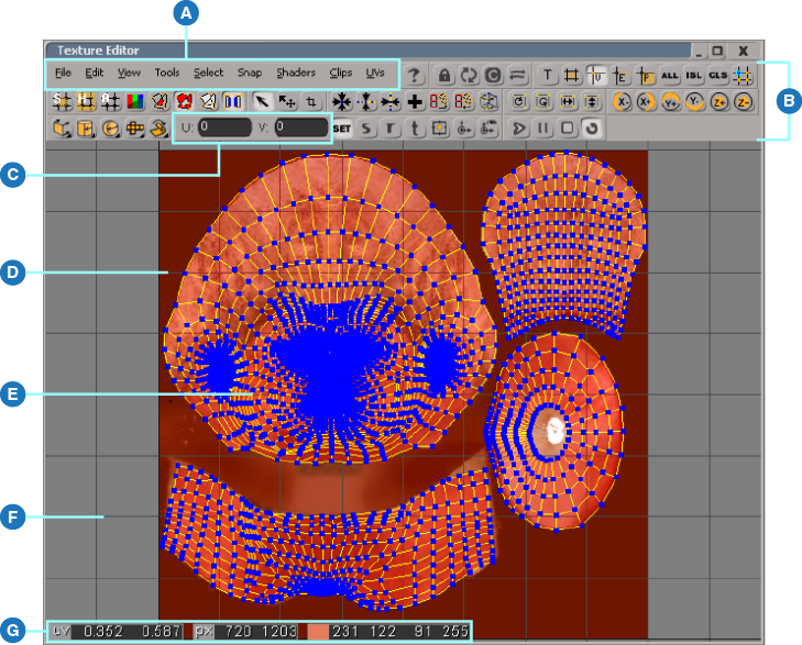
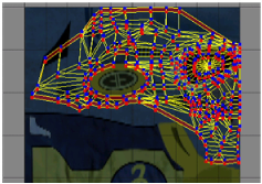
The first time you open the texture editor with a complex object selected, you may be overwhelmed. The texture editor displays a two-dimensional representation of the selected objects' geometry superimposed on a texture that image. The more complex an object, the more complex its appearance in the texture editor.
Select the object(s) whose UV coordinates you wish to display in the texture editor.
Choose Texture Editor from any viewport's Views menu, or choose View  Rendering/Texturing Texture Editor from the main menu to open the texture editor.
If you selected a single object with multiple texture projections, only its current UV coordinate set is displayed. You'll have to toggle the display of other coordinate sets, as described in Choosing UV Coordinates to Display.
If you selected multiple objects, each object's default UV coordinate set is displayed. All visible UV coordinate sets are editable. See Editing Multiple UV Sets for details.
If necessary, frame the entire texture in the texture editor by selecting View Frame Image (or by pressing Shift + I).
If desired, change the texture image that's displayed, as described in the following section.
Choosing a Texture Image to Display
The texture editor's Clips menu allows you to choose the image clip that is displayed in the texture editor workspace, as well as on the object in the 3D views in Textured and Textured Decal display modes while the texture editor is open. It contains an alphabetical list of all of the image clips used by the selected object(s). Choosing different clips allows you to see how the same set of UV coordinates maps different textures onto an object.
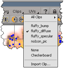
The Clips menu gives you the following options:
The All Clips submenu lists of all the image clips in the scene alphabetically. Choose one of these clips to display it in the texture editor workspace as well as in the 3D views.
Auto displays the image clip associated with the UV coordinates currently selected for editing. If this is on when you select a different object in the scene and update the texture editor, the texture editor automatically displays the appropriate clip. Explicitly selecting a different clip toggles the Auto option off, but you can choose Auto again to toggle it back on.
The alphabetical list of clips includes all clips applied to the objects whose UVs are currently displayed in the texture editor. Choose one of these clips to display it in the texture editor workspace as well as in the 3D views.
None displays the UV coordinates in the texture editor workspace with no texture image at all.
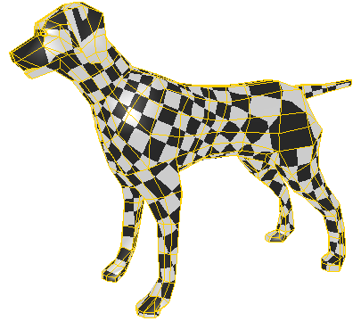
Checkerboard displays a checkerboard image in the texture editor workspace as well as in the 3D views. This is useful for seeing how the texture image gets stretched over different areas of an object. See Displaying the Checkerboard.
Import Clip opens a browser from which you can choose an image to import as a new clip/source pair. For more information about image clips and sources, see Managing Image Sources & Clips.
If you're having trouble seeing a projection's UV coordinates in the texture editor workspace, you can dim the texture image to make the coordinates more visible.
You can display a checkerboard image in the texture editor workspace, as well as on objects in the 3D views in Textured and Textured Decal display modes while the texture editor is open. This is useful for seeing how the texture image gets stretched over different areas of an object. An even distribution of regularly sized squares indicates minimal stretching, which is usually preferable, although you may want a higher density of squares in areas of high detail such as the face of a character.
Choosing UV Coordinates to Display
In the texture editor, each selected object's texture projections are listed in the UVs menu. You can use the menu to choose which set(s) of UV coordinates is displayed at any given time.
If a set of UV coordinates is displayed, it can be edited. See Editing Multiple UV Sets.
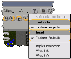
Each selected object's texture projections are listed in a section of the UVs menu. You can choose any combination of these projections to display their UV coordinates in the texture editor workspace. Shift+click to toggle individual projections on or off.
Texture Editor Toolbars and Preferences
Showing and Hiding Texture Editor Toolbars
The texture editor command bar is made up of several different toolbars, each of which contains a different set of commands. Depending on how frequently you use these commands, you may wish to hide some of the toolbars. The state of each toolbar is persisted between sessions, so any toolbars that you hide remain hidden until show them again, even if you restart Softimage.
Setting Texture Editor Preferences
You can change the behavior and appearance of the texture editor by changing a number of preferences located in the Texture Editor preferences property editor. Refer to Texture Editor Preferences for information about individual preferences.
Useful Texture Editor Display Options
As you work with UV coordinates in the texture editor, you'll find several of the display options indispensable for the information they provide about coordinate selections. Some of these options are described in this section.
When you open the texture editor, the object's UV mesh may be difficult to see in some areas. To see more clearly where the object's UV coordinates cover the texture image, you can highlight the covered areas of the texture image.
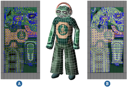
Highlighting texture coverage (B) allows you to see more clearly where an object's UV coordinates lie on the texture image. (A) shows the unhighlighted coverage for comparison.
To highlight areas of the texture covered by UV coordinates
Click the Highlight Coverage button  in the texture editor command bar.
From the texture editor menu, choose View Show Coverage.
You can modify the appearance of coverage highlighting by changing the Coverage preferences on the Highlighting tab of the Texture Editor Preferences property editor.
For more information about setting texture editor preferences, see Setting Texture Editor Preferences.
Highlighting Overlapping UV Coordinates
To help you get a better idea of exactly how an object's UV coordinates are laid out on a texture image, you can highlight the areas of the image where the coordinates overlap. Two overlap highlighting modes are available:
Highlight Overlaps highlights areas of the image where the object's UV coordinates overlap. Generally, these tend to be problem areas where the UV coordinates need adjustment. Highlighting overlaps helps you identify these areas quickly.
Highlight Odd Overlaps highlights areas of the image that are covered an odd number of times by the object's UV coordinates. This can help you identify areas where symmetric texture mapping isn't quite perfect, because only the areas where the UV coordinates don't overlap are highlighted.
The overlap highlighting modes cannot be used together, though either one can be used in conjunction with coverage highlighting.
To highlight areas of the texture that are covered an odd number of times
Click the Highlight Odd Overlaps button in the texture editor command bar.

From the texture editor menu, choose View Show Odd Overlaps.
You can modify the appearance of overlap highlighting by changing the Overlaps preferences on the Highlighting tab of the Texture Editor Preferences property editor.
For more information about setting texture editor preferences, see Setting Texture Editor Preferences.
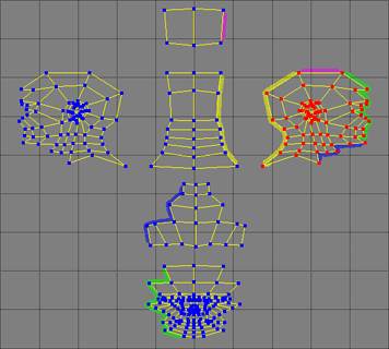
Working a polygon object in the texture editor often means breaking up its UV mesh into different UV coordinate islands that you'll reassemble later. Each island's boundaries correspond to other islands' boundaries wherever their component polygons share an edge on the object. You can turn connectivity tabs on in the texture editor to highlight these corresponding boundaries.
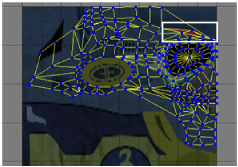
Connectivity tabs highlight corresponding pairs of UV island boundaries in different colors, allowing you to easily pair up the boundaries that you want to reassemble. This is especially helpful when you're reassembling the islands using the Island Heal tool (see Healing Polygon Islands).
If you prefer that all connectivity tabs be the same color, change the Color preference in the Connectivity options on the Highlighting tab of the Texture Editor Preference property editor.
For information about setting texture editor preferences, see Setting Texture Editor Preferences.
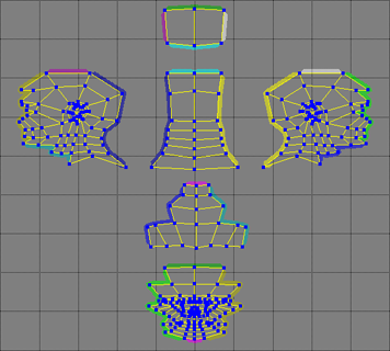
By default, connectivity tabs are displayed only for selected sample points (and those on their corresponding boundaries). However, you can also display them on the entire UV set to see all of the corresponding boundaries at once.
You can modify the appearance and behavior of connectivity highlighting by changing the Connectivity Tabs preferences on the Highlighting tab of the Texture Editor Preferences property editor.
For more information about setting texture editor preferences, see Setting Texture Editor Preferences.