Choosing the right type of texture projection is an important part of the texturing process. The more closely the projection conforms to the shape of the object, the less you'll have to adjust the texture to get the object looking just right. This section describes the types of texture projection that are available to you:
Cylindrical projections project a texture from a virtual cylinder around an object toward the central axis of the cylinder.
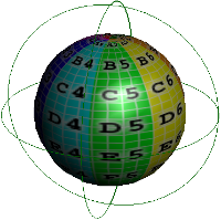
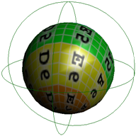
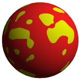
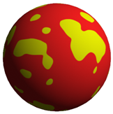
Spherical projections map a texture onto an object similarly to a beachball, with some distortion at the +Y and -Y poles.
A lollipop projections wraps the texture around the top of an object, with the corners meeting at the bottom like the wrapper of a lollipop. To apply a lollipop projection, you must use the TextureWizard as described in Using the TextureWizard.
UV Projection (NURBS Surfaces Only)
UV projections follow the UV parameterization of NURBS surface objects (no relation to texture UV coordinates). A UV projection behaves like a rubber skin stretched over the object's surface. The points of the object correspond exactly to a particular coordinate in the texture, allowing you to accurately map a texture to the object's geometry.
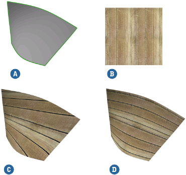
A NURBS surface with a wood texture applied using an planar XZ map and UV map. With the UV map applied, the pattern accurately follows the contours of the object.
A camera projection projects a texture from the camera onto the object's surface, much like a slide projector does. This is useful for projecting live action backgrounds into your scene so you can model and animate your 3D elements against them.
Changing the camera's position changes the projection's position. Once you have positioned the texture on the surface to your liking, you can freeze the projection.
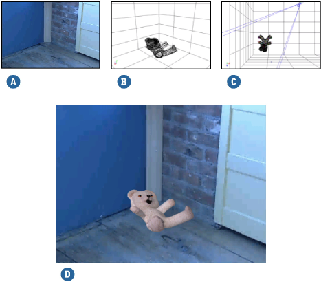
The corner of a room was textured using a texture image that was projected from a scene camera. The rendered result shows the modeled teddy bear against the projected background.
| A |
Texture image used |
| B |
Wireframe view of the rendered frame |
| C |
Top view showing where the texture is projected |
| D |
Final rendered frame |
Select the elements to texture (one or more objects, groups, hierarchies, polygons, or polygon clusters) and then choose Get  Property Texture Projection Camera Projection from any toolbar.
In a texture shader's property editor, choose New Camera Projection in the Texture Projection group box.
In a texture shader's property editor, choose New Create New Projection in the Texture Projection group box, then set Projection Type to Camera in the TextureWizard and click OK.
Navigate the camera or transform the objects in the scene so that the texture fits properly. You can use the render region in the camera view to verify the rendered result.
Once the projection is to your liking, you can freeze the projection to stop the texture from following the camera when it moves. For more information about freezing texture projections, see Freezing Texture Projections.
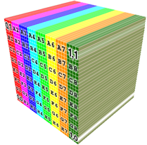
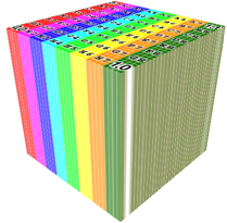
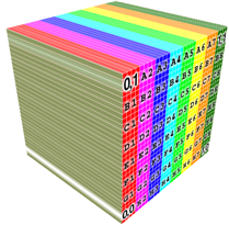
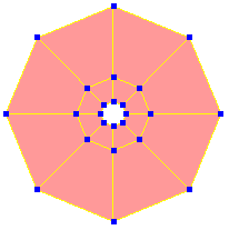
When you apply a cubic projection to an object, the object's faces are assigned to a specific face of a cubic texture support, based either on the orientation of their polygon normals or their proximity to a face. The texture is then projected from each face of the support using a planar or spherical projection method.
By default, the entire texture is projected from each of the cube's six faces. However, you can choose from a number of different cubic projection presets. You can also transform each face of the cube individually and save the transformations as presets of your own.
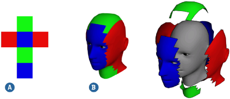
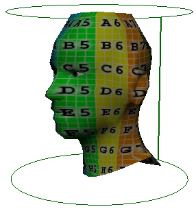
A cubic projection is applied to a head (B) so that a different part of the texture image (A) is projected onto each face. In this case the preset used was Cubic_verticalcross.
Select the elements to texture (one or more objects, groups, hierarchies, polygons, or polygon clusters) and then choose Get Property Texture Projection Cubic from any toolbar.
In a texture shader's property editor, choose New Cubic in the Texture Projection group box, and then click Edit.
In a texture shader's property editor, choose New Create New Projection in the Texture Projection group box, then set Projection Type to Camera in the TextureWizard and click OK. Finally, click Edit in the Texture Projection group box.
By default, the entire texture is projected from each of the cube's six faces. If that's not what you want, the first thing is to select a different configuration. Do one of the following:
On the Layout tab, click Load Preset and select a saved preset from the browser.
On the Custom tab, configure each of the cube's faces independently. If desired, you can save a preset of your custom configuration by clicking Save Preset on the Layout tab.
Set the other options as desired, in particular Face Selection and Face Projection. For a description of all options, see Texture Support Property Editor.
A spatial projection is a three-dimensional UVW texture projection that projects through an object's volume. It is typically used with procedural 3D textures for materials that have internal structure like wood, marble, and so on. If you deform the object or transform the texture support relative to the object, different parts of the internal texture are revealed.
|
|
| The texture support for the vein texture was translated slightly to the right, showing how the veins change shape, merge, and diverge internally. |
|
Unique UVs Projection (Polygons Only)
Unique UVs mapping applies a texture to polygon mesh objects using one of two possible methods:
Individual polygon packing assigns each polygon's UV coordinates to its own distinct piece of the texture so that no one polygon's coordinates overlap another's.
This is useful for rendermapping polygon meshes. Typically, you apply textures to an object using a projection type appropriate to its geometry. Then you can rendermap the object using a new Unique UVs projection to output a texture image that you can reapply to the object. The texture is applied to texture each polygon properly without you worrying about "unfolding" it to fit properly.
A polygon-packing style Unique UVs projection only produces good results if you use a texture created specifically for the projection, for example, an image created using Render Map.
Angle Grouping, after deciding on a projection direction, groups together neighboring polygons whose normal directions fall within a specified angle tolerance. This process is repeated until all of the object's polygons are in a group. The groups — or islands — are then assigned to distinct pieces of the texture so that no two islands' coordinates overlap each other.
Contour Stretch UVs Projection (Polygons Only)
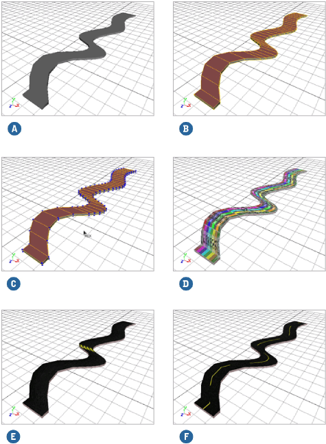
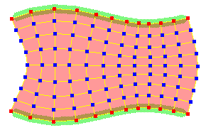
Contour Stretch UVs projections allow you to project a texture image onto a selection of an object's polygons. Rather than projecting according to a specific form, a contour stretch projection analyzes a four-cornered selection to determine how best to stretch the polygons' UV coordinates over the image.
Contour stretch projections do not have the same alignment and positioning options as other projections. Instead, you select a stretching method that is appropriate to the selection's topology and complexity. Also, contour stretch projections do not have a texture support. You can adjust them only from the texture editor.
Contour stretch projections are useful for a number of different texturing tasks, particularly for applying textures to tracks and roads on irregular, terrain-like meshes. They are also useful for fitting regular-shaped textures onto curved meshes. For example, they would be useful to place a label texture on a beer bottle, right at the junction of the bottle's neck and body.
Although the easiest geometry to contour stretch is a rectangular grid of quads, it's more likely that you'll want to use contour stretch projections on less regular shapes. This is not a problem as long as you keep a few simple guidelines in mind when you make your selection.
The selection cannot be a whole object: it must be a selection of polygons with an identifiable contour.
Although the selection doesn't have to be perfectly rectangular, the contour stretch projection must be able to derive four corners from its contour.
If the selection has holes in it, it is more likely to produce undesirable results.
If the selection consists of two or more discontiguous "islands," their UV coordinates do not remain separated in the texture editor once the projection is applied. Instead, they are treated as a single, one-piece selection.
Applying a Contour Stretch UVs Projection
Select any number of polygons on the object to which you want to apply the contour stretch projection.
Remember that the selection must have four discernible corners (even if it isn't perfectly rectangular) and a clear contour.
From the Render toolbar, choose Get Property Texture Projection Contour Stretch UVs.
The selection's corners are automatically detected, the object's points are displayed, and a pick session begins.
If necessary, pick new corners for the polygon selection to which you are applying the projection. The new corners must lie on the boundary of the initial polygon selection. Then right-click to end the pick session.
Right-click to end the pick session and use the automatically detected corners.
Choose a contour stretch method and set any other options as desired. See Poly UV Contour Stretching Property Editor [Properties Reference].
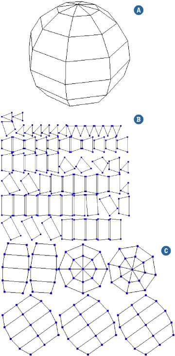
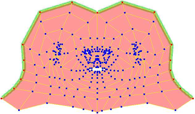
Unfolding creates a UV texture projection by "unwrapping" a polygon mesh object using the edges you specify as cut lines or seams. When unfolding, the cut lines are treated as if they are disconnected to create borders or separate islands in the texture projection. The result is like peeling an orange or a banana and laying the skin out flat.
Unfolding a Texture Projection
Select a polygon mesh object. If desired, you can also select edges to use as cut lines (remember to click Add to Cut Line in step 3). Whether or not you select edges now, you can still add and remove cut lines later in the procedure.
You can also select an existing texture projection if you want to add the Unfold operator to it instead of creating a new projection. Any existing texture seams will be automatically added as cut lines for the unfold operation. This lets you start with an existing projection then add cut lines and re-unfold, or simply use the packing options to arrange the islands.
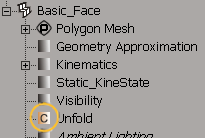
Choose Get Property Texture Projection Unfold.
An Unfold property is applied to the mesh and its property editor opens. For a description of all the options in this property editor, see Unfold Property Editor.
Define the edges to use as cut lines:
Select some edges and click Add to Cut Line. Repeat to add more edges.
If you added some edges that you don't want, select them and click Remove from Cut Line.
To start over with a completely new set of edges, select the desired edges and click Set from Current Edges.
To see the edges that are currently set as cut lines at any time, click Select Cut Line.
For some tips, see Tips for Choosing Cut Lines.
When you have set the desired cut lines, click Unfold and Pack.
Open the texture editor (Alt+7) or refresh it to see the result of the unfolding. Note that if the object already had a UV texture projection, then you may need to select the Unfold projection from the UVs menu.
If desired, you can continue to adjust the cut lines as in step 3. Click Update and Pack or Update No Pack to see the results in the texture editor.
Any new seams that you create by tearing polygons in the texture editor are automatically added as cut lines.
If you want to concentrate on one or more islands at a time, then you can re-unfold those specific islands without affecting
others. In the texture editor, select the desired islands and choose Tools Re-Unfold Selected Islands (Unfold Op Only). This command works only if you have used this procedure to unfold the mesh, that is, if there is an Unfold operator in its
texture projection stack.
You can also make other changes to the UV coordinates in the texture editor. For example, you may want to relax or regularize different regions as described in Relaxing and Regularizing Sample Points.
If desired, use the options on the Packing tab to control how the UV islands are laid out in UV space. You can either set these options and then click Pack, or activate Live packing to see the effects as you make changes.
Alternatively, you can adjust the packing by manually translating the islands in the texture editor.
If you need to make changes later, you can re-open the Unfold property from an explorer:
If you are completely satisfied with the unfolding and certain that you will never need to change it, you can freeze the texture projection.
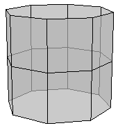
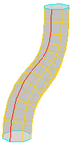
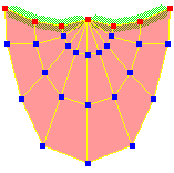
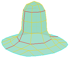
The principal goal for choosing cut lines is to minimize the amount of distortion when the mesh is flattened out. For example, if you simply flatten an open cylinder, there is an undesirable distortion in the size of the polygons.
|
|
In addition, you should try to minimize the number of islands and the lengths of the cut lines as much as possible. This results in less work for the texture painter when smoothing the change of color across the seams. You should also try to place cut lines where they will be less visible, for example, under the arms or behind the head, so that any problems at the seams will be less noticeable.
Here are some general guidelines for minimizing distortion. However, the final choice of cut lines depends greatly on the shape of the specific object.
For tube-shaped islands, add a cut line along the length.
|
|
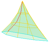
For conical islands, add a cut line from the tip to closest boundary.
|
|
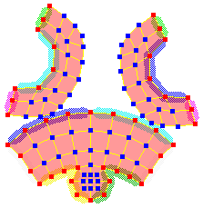
For sock-shaped islands, add a cut line along the length with a partially detached "cap".
|
|
Holes in islands can sometimes cause distortions. If this occurs, try splitting the islands to remove the holes.
If you receive errors when applying or updating an Unfold projection, check for unusual geometry such as double edges, double polygons, and so on. Occassionally, even polygons with 5 or more sides can cause problems.
Some shapes cannot be unfolded well without being cut into many islands. For example:
The Freeze M button (freeze modeling) does not freeze the Unfold operator in the texture projection stack. To freeze it, do either of the following:
Select the Unfold projection or UnfoldOperator in the projection stack (not the Unfold custom property) in an explorer and click Freeze. For more information, see Freezing Texture Projections.
Freezing the Unfold operator does not remove the Unfold custom property on the object. If the operator has been frozen, then using the buttons in the Unfold property editor will create a new set of UV coordinates.