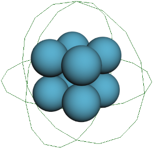
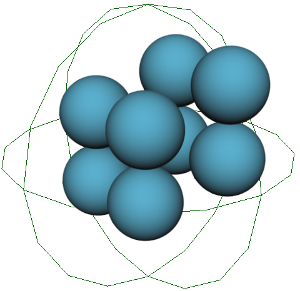
Creates and emits particles, filling the volume of one or more emitter objects. This compound is useful for most types of fluid effects where you want to consider the volume of a substance upon emission, or simulate a large volume of points that can break apart and show the volume's inner points.
Particles are emitted in a rest state with space between them so that they do not collide upon emission. The particle's mass value (based on the particles Mass attribute) is assumed to be 1 so that forces can act upon them accordingly.
See Setting Up Emissions in Lagoa Simulations for more information.
Plug this compound's Execute output into a port on the ICETree node or in an Execute port on a Simulation Root node.
| Resolution Per Unit |
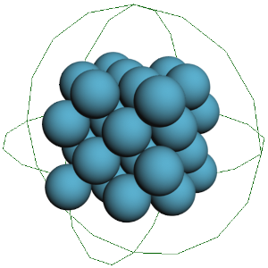
To calculate the emission of elements, the emitter's volume is divided into Softimage units, each representing a fixed space of 10 cm. This parameter sets the density (points per unit ratio) of the element, adjusting the size and number of points for each unit of the emission volume. It tries to put in as many points of mass as can fit inside the emitter volume's space. The points are arranged into a neat grid within this volume upon creation. A value of 1 means that one point is created per unit inside the volume. A lower value means that the density that is trying to be achieved per unit will require more (and smaller) points to fill the same volume. See Setting Up Emissions in Lagoa Simulations for more information. |
| Max Cells |
Maximum number of cells that can be created. Cells are subdivisions of the units. The default maximum is 1,000,000 cells. Using a Resolution Per Unit value of 0.01 creates 1,000,000 cells. |
| Generate |
The way in which the points are generated inside the volume:
This is useful for creating fluid effects, when you need many particles, but you don't want to lower the Resolution Per Unit value. It's also the best choice if you want to simulate volume-preserving soft bodies. Tetrahedra may require more substeps because they have more resolution by default. |
| Emit Rate |
Emits the points in either way: |
| Emit at Frame |
The frame at which the particles are emitted if you selected Once at Frame as the Emit Rate option. |
| Global Time |
If this option is on, Emit at Frame is relative to the scene's timeline. If it is off, the frame is relative to the simulation range set in the Simulation Time Control Property Editor. |
| Color From |
The color of the points at emission coming from either: |
| Color |
The display color of the points only at emission. This color is overridden when you select the Set Color option the color set in the Material compound (see Lagoa Material Cloth). Setting the color in the Material compound lets you update the point color at every frame instead of only at emission. |
| Shape |
Shape of the particles at emission. This uses the particle's Shape attribute. You can also used instanced geometry as the particle shape. |
| Node Type |
Make sure this is set to Real. The other values are available for future functionality. |
| Cluster ID |
Sets the cluster for points emitted from the connected object. Points in clusters with different IDs will not attach to each other during the simulation. |
| Cluster at Emission |
Considers the particles at emission time to be a separate cluster so that at every frame a new cluster is created independently from the existing ones. See Creating Elastic Clusters for more information. |
| Cluster by Geometry |
With elastic structures, this option considers each geometry to be a separate cluster that does not merge with the others. For example, you may want to emit two different volumes that are in their own clusters instead of merging them together. To merge clusters, they need to have the same Cluster ID, then select the Solve Plasticity option in the Lagoa Simulate Multiphysics node. |
| Constrainable |
Toggles the activeness of the particles' constrainability. Particles that are constrainable can stick to a collision object's surface (contact links — see Lagoa Material Cloth) and can have constraints turned on/off. |
| Phase |
The Phase ID of the particles where they are initialized. This ID must match the Emit node's accompanying Lagoa Phase node. |
| Initial Force |
The force direction given to the particles at emission. This can be in any direction (XYZ). |
| Execute on Emit |
Any node plugged in here is executed only at emission. |