IK solvers are the mathematical algorithms behind the IK handles. IK solvers calculate the rotations of all the joints in a joint chain controlled by an IK handle. The effect an IK handle has on a joint chain depends on the type of IK solver used by the IK handle. By default, Maya loads the following IK solvers on start-up:
See Single Chain solver and Create a single chain IK handle.
See Rotate Plane solver and Create a rotate plane IK handle.
You can use the spline IK solver only in conjunction with a spline IK handle. See Spline IK solver, Tips for working with spline IK handles , and IK Spline Handle Tool.
The human IK solver is only used by characters that have been characterized. You cannot use the hikSolver with regular IK handles.
In addition to the default solvers, you can create the following solvers:
Before you can use the 2 bone IK solver, you first need to manually load and activate it in Maya. See 2 Bone solver and Create a 2 bone solver.
To create the multi-chain IK solver, use the createNode MEL command. See Multi-chain solver and Create the multi-chain solver.
Before you can use the spring IK solver, you first need to activate it in Maya. See Spring IK solver and IK Spring Solver Attributes.
If you want to pose and animate joint chains that have between two and four joints, use single chain or rotate plane IK. If you want to pose and animate longer joint chains, use spline IK. If you want to pose and animate simple three joint IK chains for use in games, use 2 bone IK.
By default, each IK handle you create that uses the same type of IK solver, also shares the same IK solver node. For example, all IK handles that use single chain IK also connect to the same ikSCsolver node. Consequently, if you edit the attributes of the shared IK solver node, all the IK handles that connect to the node are affected. If you want to fine-tune the IK solvers for certain IK handles only, while not affecting other IK handles, you can create additional IK solvers for your IK handles using the createNode MEL command.
When you move an IK handle, the solver performs the appropriate calculations to move and rotate all the joints in its IK chain accordingly. First, the solver looks at the position (Translate X, Y, and Z attributes) and orientation (Rotate X, Y, and Z attributes) of the IK handle. Next, the solver calculates how to move the position and orientation of the end effector as close to the IK handle’s position and orientation as possible. To do that, the solver calculates how to best rotate the joints in the IK handle’s joint chain. Finally, the solver then rotates all the joints in the joint chain so that the end effector reaches the IK handle’s position and orientation.
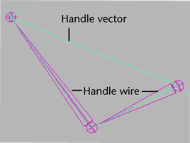
A single chain IK handle uses the single chain solver to calculate the rotations of all the joints in the IK chain. Also, the overall orientation of the joint chain is calculated directly by the single chain solver.
Difference between single chain and rotate plane IK handles
The difference between a single chain IK handle and a rotate plane IK handle is that the single chain IK handle’s end effector tries to reach the position and the orientation of its IK handle, whereas the rotate plane IK handle’s end effector only tries to reach the position of its IK handle. Since the rotate plane IK handle’s end effector only tries to reach the position of its handle, the resulting joint rotations are more predictable. For the rotate plane IK handle, the orientation of its entire joint chain is controlled by the twist disc manipulator. For more information, see Twist disc and Rotate Plane solver.
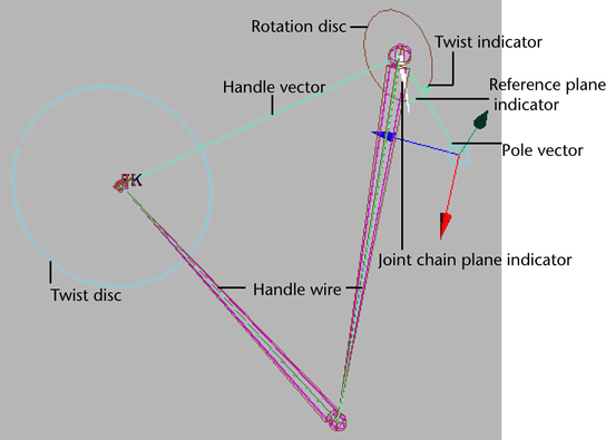
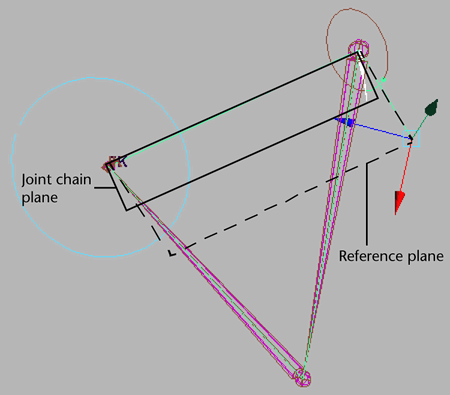
A rotate plane IK handle uses the rotate plane solver to calculate the rotations of all the joints in its IK chain, but not the joint chain’s overall orientation. Instead, the IK rotate plane handle gives you direct control over the joint chain’s orientation via the pole vector and twist disc, rather than having the orientation calculated by the IK solver. The single chain solver and rotate plane solver differ in this respect. See Difference between single chain and rotate plane IK handles.
The rotate plane solver is ideal for posing joint chains (such as arms and legs) that you want to stay in the same plane. For example, the shoulder, elbow, and wrist joints of an arm driven by a rotate plane IK handle all stay within the same plane as the elbow rotates. The plane itself can be rotated from the shoulder joint by the pole vector. See Pole vector and Twist disc.
Rotate Plane IK handle components
The twist disc is a manipulator that you can use to twist or rotate the joint chain. The twist disc is located at the end joint of the IK chain.
Translating the pole vector often leaves the IK chain pointing in the wrong direction. You can use the twist disc to re-orient the plane after you move the pole vector to prevent flipping. To view an image of the twist disc, see Rotate Plane solver.
The joint chain plane is the plane that contains all the joints in the joint chain and poses through the axis. The joint chain plane rotates about the handle vector. When you manipulate the pole vector, you are rotating the joint chain plane about the handle vector. To view an image of the joint chain plane, see Rotate Plane solver.
For the joint chain plane to rotate and twist the joint chain, the plane must rotate relative to some other plane so that the degree of twist can be measured. The plane that the joint chain plane rotates relative to is the reference plane. To view an image of the reference plane, see Rotate Plane solver.
The pole vector is a manipulator that lets you change the orientation of the IK chain. The pole vector also lets you control flipping.
Since moving the pole vector changes the orientation of the reference plane, moving the pole vector can also change the orientation of the joint chain directly; just as manipulating the twist disc can change the orientation of the joint chain. This is because the joint chain’s degree of orientation—or twist—is defined as the difference in orientation between the reference plane and the joint chain plane. To view an image of the pole vector, see Rotate Plane solver.
When positioning your IK handle, if the handle vector and the pole vector cross each other or point in exact opposite directions, the joint chain can suddenly flip. You can prevent this flipping by moving the pole vector so that the handle vector does not cross it or point in the opposite direction from it.
The rotation disc is an indicator that displays how much the IK chain has been rotated by the twist disc. The rotation disc is located at the start joint of the IK chain. To view an image of the rotation disc, see Rotate Plane solver.
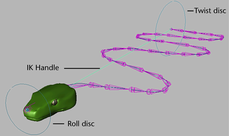
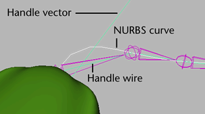
Spline IK handles let you pose a joint chain using a NURBS curve. When you manipulate the curve, the handle’s spline IK solver rotates the joints in the chain accordingly. You can use spline IK to pose and animate long, sinuous joint chains such as those for a tail, a tentacle, a snake and so on.
See also Tips for working with spline IK handles .
See Twist disc.
The roll disc is a manipulator that lets you roll or rotate the entire spline Ik joint chain. The roll disc is always at the spline IK handle’s start joint. The roll disc is similar to the rotation disc and pole vector. See General IK handle components.
With the spline IK twist control attributes, you can constrain the local rotation of the joints in a chain to a fixed worldspace vector. This vector is the orientation of the spline IK NURBS curve. For example, you can use the advanced spline IK twist controls to stabilize a snake character, the spine of a biped character, or the movements of a coil spring. Also, to fine-tune the twist along the chain, you can add additional twist to the joints with the Twist Value attributes.
By aligning the joints Up axes with a fixed worldspace vector before applying additional twist, you can achieve a more predictable and stable result than was previously possible.
See Use the advanced Spline IK twist controls and Add Advanced Twist Control Attributes.
IK handles with spline IK let you pose your joint chains using NURBS curves. When you manipulate the spline IK curve, you are moving and rotating all the joints in the target IK chain. An easy way to manipulate the spline NURBS curve is to create a cluster deformer for each of the curves CVs. See Edit Curves > Selection > Cluster Curve in the Modeling NURBS guide.
Spline IK handles are ideal for posing and animating long joint chains like those for tails, tentacles, necks, spines, and similar objects.
The start joint of your spline IK joint chain can sometimes flip when you move or rotate the spline IK curve or its CVs, or when you slide the joint chain along its curve. The flipping is a normal result of the spline IK solver’s calculations.
Joint flipping occurs when the orientation of a joint is more than 90 degrees from its rotation value of 0. A joint’s rotation value is 0 when its Rotate X, Y, and Z values are 0, relative to its parent joint’s rotation values. Flipping is most pronounced when a joint nears 180 degrees rotation.
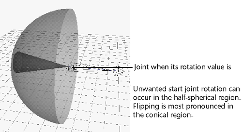
You can prevent start joint flipping by moving each of the joints after the start joint to roughly their rest positions. See Prevent flipping in the spline IK chain.
Unwanted start joint flipping can also occur when you animate a joint chain along its curve, for instance, when you slide a snake along a motion path.
If you have positioned joints appropriately and joint flipping still occurs, parent the start joint to another joint or to a transform node. See Auto Create Root Axis and Auto Parent Curve.
The 2 bone IK solver is a subset of the rotate plane IK solver. Therefore, IK handles with the 2 bone IK solver solve the rotations of their joint chains in the same manner as a rotate plane IK handle. See Rotate Plane solver and Rotate Plane IK handle components.
The two bone IK handle is meant for posing and animating short joint chains that consist of three joints (two bones). If you try to pose and animate a longer joint chain with the two bone IK handle, then the 2 bone solver will solve for the rotations of only the start and second to last joints and will ignore all other joints in the joint chain.
The 2 bone solver is ideal for posing joint chains (such as arms and legs) that you want to stay in the same plane. For example, the shoulder, elbow, and wrist joints of an arm driven by a rotate plane IK handle all stay within the same plane as the elbow rotates. The plane itself can be rotated from the shoulder joint by the pole vector. See Pole vector.
The 2 bone solver is the fastest IK solver in Maya. This makes two bone IK handles ideal for setting up characters in a games development environment. Maya includes the source code for the two bone IK solver plug-in so that game developers can replicate the exact behavior of this feature in a games engine or modify the code to create their own custom IK solvers.
IK two bone solver plug-in source code
The source code for the two bone IK solver is available in the devkit’s ik2Bsolver directory. The source code provides an example of how you can create your own IK solver plug-in. Also, by extracting the core algorithm, you can replicate the exact behavior of the 2 bone IK solver in a games engine. For more information, please read the README file in the ik2Bsolver directory.
The multi-chain solver can solve for multiple IK handles simultaneously. You can use the multi-chain IK handles to animate complex motions such as those of the tentacles of an octopus character.
An IK handle with the multi-chain solver manages the joints in its joint chain in the same manner as a single chain IK handle. See Single Chain solver.
The IK handle's Priority and Weight attributes apply only to the multi-chain IK solver. See ikMCsolver in Help > Node and Attribute Reference.
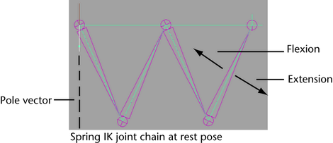
The spring IK solver (ikSpringSolver) produces proportional rotations across all joints. This is useful when posing and animating limbs that have numerous joints such as insect legs.
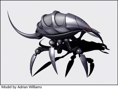
Watch: springIKinsect.mov
The spring IK solver keeps the angles between joints in its joint chain proportional by applying bias values to those angles. This ensures that the angles between all joints are always evenly distributed. The spring IK solver is similar to the rotate plane IK solver in that both their IK handles have pole vectors. Since the spring IK handle has a pole vector, flipping will occur if the spring IK joint chain crosses its pole vector.
An IK handle using the spring IK solver requires a rest pose. By default, the position and orientation of the target joint chain at the time of the spring IK handle’s creation is its rest pose. The distance between the first and last joint of a spring IK joint chain at its rest pose determines if the joint chain is flexed or extended, and influences each individual joint’s movement.
