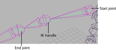
In an IK chain, the joint where the IK handle begins is called the start joint and the joint where the IK handle ends is called the end joint. All the joints between the start and end joints are driven by the IK handle and its solver. In the scene view, the IK handle is drawn as a line from the start and end joints of the IK chain.
The end of the IK handle, which is located at the last joint of the IK chain by default, is called the end effector. When you move the IK handle, the IK solver uses the end effector’s position and orientation in its calculations to rotate the joints in the IK chain accordingly. The end effector tries to follow the IK handle’s position at all times. However, depending on the rotational limits and fully extended length of the IK chain, the end effector might not be able to reach IK handle. To move the IK handle to the end effector’s position, see Animate > IK/FK Keys > Move IK to FK.

To create an IK handle, use the IK Handle Tool or the IK Spline Handle Tool. See IK Handle Tool and IK Spline Handle Tool.
To show all the current IK handle’s components, see View all IK handle components.
The handle wire is the line that runs through all the joints and bones in a joint chain controlled by an IK handle. The handle wire begins at the start joint’s local axis and ends at the end joint’s local axis.
To view an image of the handle wire, see Rotate Plane solver.
The handle vector is the line drawn from the start joint of the IK chain to the IK handle’s end joint (end effector). This is the axis used by the rotate plane.
To view an image of the handle vector, see Rotate Plane solver.