Displacement Mapping


Use displacement mapping to create a 3D model from a 2D surface. The values of a selected colour channel in the displacement source clip are used to create a displacement map. When the displacement map is applied to the surface, the pixels of the surface are displaced along the positive or negative X, Y, and/or Z axes. Displacement mapping uses the media’s matte clip, so you can turn the matte on or off to get the desired effect.

To add a displacement map:

  1. In the schematic, select the surface or 3D geometry to which you want to apply the displacement.
  2. Click Media.
  3. In the Media menu, select the media you want to use for the displacement.
  4. Do one of the following:
    • Drag the Displace Map node from the Maps tab of the node bin and place it in the schematic.
    • Drag the Displace Map node from the Maps tab of the node bin and place it where you want it in Result view.
    • Double-click the Displace Map node. You do not need to be in Schematic view to add a node in this manner.

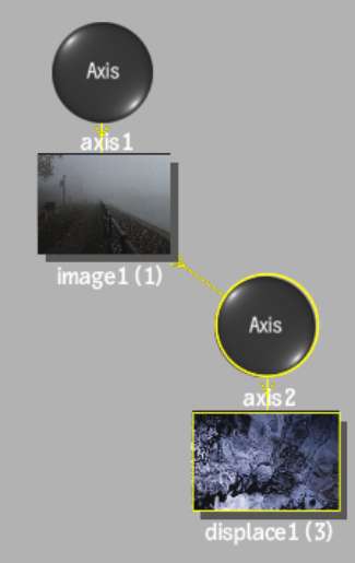
    The displace object is added to the schematic with its own parent axis. The new axis is the child of the selected surface or geometry. In Schematic view, the number in brackets next to the name of the displace node indicates the media used for the displacement.

    Show small imageShow large image

    To specify different media as the displacement source, select the media in the Media menu, then click Apply.

  5. Double-click the Displace node in the schematic, or follow the tab population rules for the Object menu (see Populating Menu Tabs of Selected Objects).

    The Displacement menu appears.