Populating Menu Tabs of
Selected Objects
Depending on what type of object is selected in the schematic, the tabs in the Object menu are populated based on different rules, as illustrated in the following examples.
An object’s name appears on the Object menu tab as well as beneath its node in the schematic and as a folder in the Channel Editor.
The Axis menu of the selected axis appears on the left side of the Object menu, and a limited number of the children objects' menus appear on the right side of the Object menu. The children objects are identified by scanning the hierarchy of the schematic from top-to-bottom (starting at the selected axis). The hierarchical scanning stops for any given branch when a non-axis object is encountered.
The order of tabs is determined on a per branch basis; that is, all of the tabs of one branch are listed before moving to another branch, starting with the highest levels in the parenting hierarchy (lowest index levels).
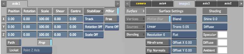
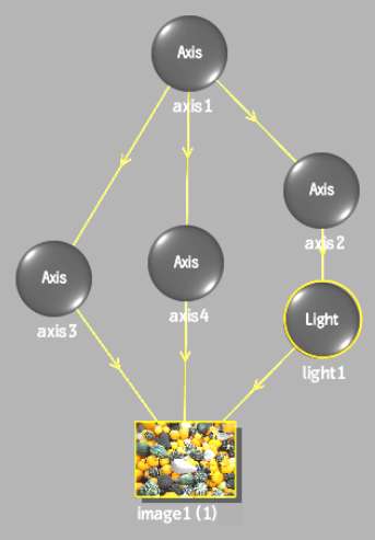
For example, in the following schematic, Axis 1 is selected.


The tabs in the Object menu appear as follows. The image1 tab appears in light blue to signify that multiple objects are connected down to it. Use the tabs to switch between menus within the Object menu. The Camera tab appears in orange as the first tab on the right side of the Object menu, and is exempt from the tab population rules.
Other object selected (no “axis attributes”)
These objects include generators, bouncers, deformations, surfaces, texture maps, shadows, geometries, and 3D text. When one of these objects is selected in the schematic, an ascending (bottom-to-top) scanning of branches is performed. The hierarchical scanning stops for any given branch when an axis or object with axis attributes is encountered.
The menu of the selected object appears on the right side of the Object menu, and a limited number of the parent objects' menus appear on the left side of the Object menu.
For example, in the following schematic, Image 1 is selected.
The tabs in the Object menu appear as follows. The image1 tab appears in light blue to signify that multiple objects are connected down to it. Use the tabs to switch between menus within the Object menu. The Camera tab appears in orange as the first tab on the right side of the Object menu, and is exempt from the tab population rules.
Object with “axis attributes” selected
These types of objects include lights, animators, projectors, and cameras. These objects trigger a different scanning behaviour depending on their position within the schematic hierarchy. If the selected object is the first of its branch (top of the hierarchy), it inherits the tab population rules of an axis, that is, descending branch scanning. If the selected object is not the top object of its branch, it inherits the tab population rules of other objects, that is, ascending branch scanning.
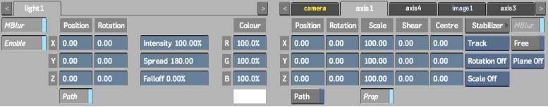
For example, in the following schematic, light 1 is selected.
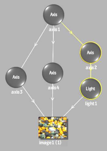
Since Light 1 is not the top object in its branch, the tabs in the Object menu appear as follows.

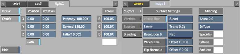
In the following schematic, light 1 is moved to the top of the branch.
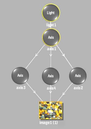
The tabs in the Object menu appear as follows. The image1 tab appears in light blue to signify that multiple objects are connected down to it. Use the tabs to switch between menus within the Object menu.