| Category | New Users |
| Time Required | 15 minutes |
| Tutorial File Used | vacuum_start.wire (created in the Set up the scene lesson) |
In this lesson you lay out the basic volume and shape of the vacuum to start this process for the project. This lesson also introduces basic interaction and organization skills.
If your vacuum_start.wire file is not currently open, use the menu item File Open to open it, or the FileOpen Recent menu, if the file is one of the last ten files opened.
Create and place the motor box volume
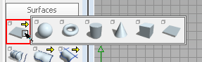
The first step in creating the vacuum is to visualize the enclosure for the motor and removable waste can. This will not be a final object, but placing a temporary object in the scene can assist in laying out other elements of the design. This also introduces transforms and pivots, as well as components and control-vertices of objects.
New. Double-click the layer name and rename the layer motorbox. This also makes the new layer the active layer. All objects are created on this layer until another layer is selected.
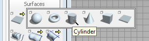
While still dragging the new cylinder around the view, press the  key to snap its centerpoint to the grid. Release the mouse button when the cylinder is near the center of the motor box in
the sketch.
key to snap its centerpoint to the grid. Release the mouse button when the cylinder is near the center of the motor box in
the sketch.
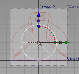
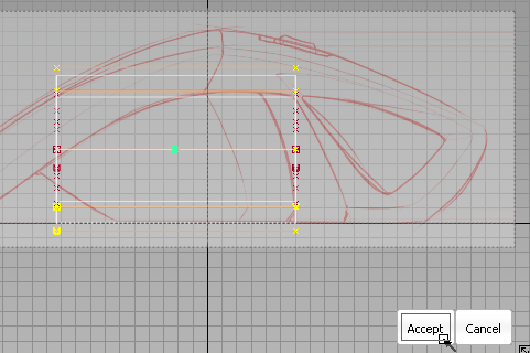
The new cylinder remains selected and the creation handles are still displayed. These handles allow easy translation, rotation, and scaling of the new object.
The arrow handles can be clicked and dragged to translate the object. The box handles allow non-proportional scaling. The dotted arcs and the sphere handles allow rotation along each axis.
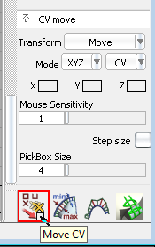
Adjust the shape of the motor box with CV edits
You can modify the shape of objects in Alias with specialized tools or object parameters, or by manipulating control vertices (CVs). The simplest method to match the volume of the sketched motor box is to taper the cylinder by manipulating its CVs.
Use the Pick Object tool to select the cylinder if it is not already picked.
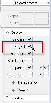
The control vertices for the three component surfaces of the cylinder display. The actual CVs are shown as yellow Xs above the surface they affect, with Hull lines shown between consecutive CVs in orange, indicating that the displayed CVs are all selected.
 +
+  +
+  ) and choose the Pick Surface tool.
The Cylinder body has four rows of CVs going down its length (the V direction). By default, the Cylinder primitive tool creates degree 3 surfaces, which require at least 4 CVs in each direction (the Cylinder has 8 CVs going around its circumference, or the U direction.).
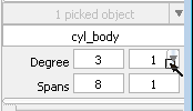
The new parameter is previewed in the workspace windows, where only two rows of CVs are now shown.
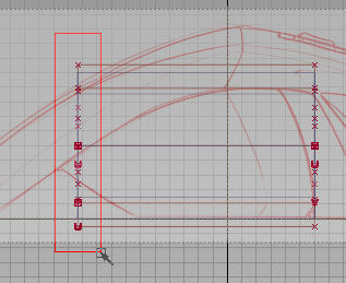
CVs from both the cylinder body and the cap surface are now picked, which is important to keep the edges of the cap and cylinder body lined up. The Pick CV tool works on all visible CVs in the scene.
. The selected CVs scale toward the object pivot (the green box currently at the center of the cylinder), and the Cylinder
both tapers and becomes shorter. 
 . This constrains the scale to the X axis, which lengthens the cylinder again, but now we know what the object pivot does.
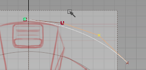
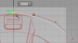
 to constrain the movement to the Y axis, and move down the selected CVs until the surface edge (the white wireframe) rests
on the X axis origin line again.
to constrain the movement to the Y axis, and move down the selected CVs until the surface edge (the white wireframe) rests
on the X axis origin line again. 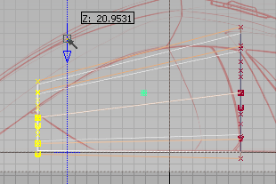
As seen in the Back view, the cylinder is too narrow for the sketch, but you can make these modifications to the whole object.
For the next few scale operations, the object pivot should be on the bottom of the object and in the center.
to constrain the pivot movement to the Z axis.
, hold down the key to magnet snap the pivot to the bottom edge of the surface (the white wireframe). 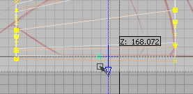 to constrain the scaling to the Z axis until the height of the cylinder matches the sketch, and then click and drag with
the to constrain the scale to the Y axis until the width of the cylinder matches the sketch (approximately).
Hardware Shade to view the volume in the scene.
to constrain the scaling to the Z axis until the height of the cylinder matches the sketch, and then click and drag with
the to constrain the scale to the Y axis until the width of the cylinder matches the sketch (approximately).
Hardware Shade to view the volume in the scene.
In the Left view, there is a slight arc to the top of the motor box volume. The surface parameters and CVs can be adjusted to add this arc.

You can create the arc to the top with the two extra rows of CVs and increased degree of the surface parameter.
 Move and click with the in the Left view to add some arch to the top of the surface.
This small part of the overall vacuum is set up. You will add more features and surfaces, but this volume can be used as reference for the rest of the process.
New, and make it the active layer.
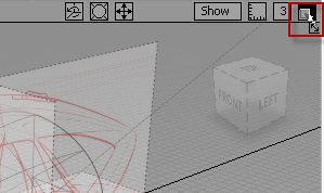
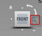
The ViewCube remains visible in these orthographic views that are accessed by clicking on a face of the ViewCube. (Proper orthographic viewing requires the ViewCube to be set to Perpsective with Ortho faces.)
If needed, use the ++ (Windows) or  ++ (Mac) navigation shortcut to Zoom until the sketch fills the view again.

When you place the fourth CV, the curve appears in white.
(By default, the New CV curve tool creates degree 3 curves, which require at least 4 CVs to define the shape).
 key (Windows), or the (Mac) to snap to the grid, and click-drag with the to constrain the movement to the Y axis
The CV easily snaps to the darker origin line without moving to a grid intersection.
Draw side profiles with edit points
The first profile curve arcs across the top of the handle from the front to the middle. This curve should intersect the first CV of the previous curve.
++ (Windows), or ++ (Mac) navigation shortcut to Zoom and ++ (Windows) or ++ (Mac) to Pan until the sketch fills the view again.
New Edit Point Curve. 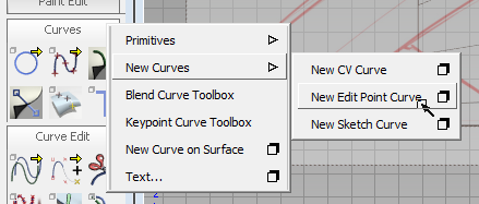
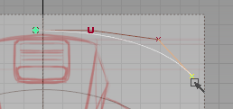
You create Edit Point curves by placing points that the curve will pass through. The CVs of the curve are placed automatically, and the curve appears after you place the second edit point.
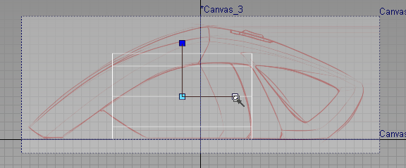
key and click with the to grid snap the initial edit point at the front edge.
-click and drag to place the second point along the front edge in the sketch, then hold the key down to magnet snap the third edit point to the initial CV of the previous curve (represented by a red box). 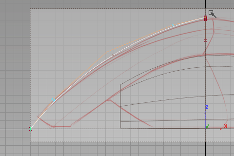 -click and drag two more edit points to the back of the sketch to define the back curve at the top edge.
  (Windows) or (Mac) key to activate grid snap, and click to place 5 new CVs along the bottom profile in the sketch, as shown in the following image.
 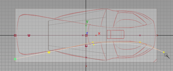 Save As to save your file with the new name vacuum_part2.wire in the project folder, rather than overwriting the initial vacuum_start.wire file of the scene.
Now that , Objects, Curves, CVs and basic picking and transformations are familiar, you can create more advanced surfaces in the Create and evaluate surfaces section.


