| Category | New Users |
| Time Required | 15 minutes |
| Tutorial Files Used | VacuumTop.jpg, VacuumLeft.jpg, and VacuumBack.jpg images from ..Alias2013\Help\CourseWare\pix |
In this lesson, you set up the Alias environment and create a file that is ready for you to start modeling.
The Alias interface is flexible and customizable. You can set up the interface and input options to your preferences. For this set of tutorials, use the options set in this section. These settings are used in the videos and screen images.
Set the position of the Palette and Shelf on your screen
This set up is optional, but highly recommended if you are unfamiliar with the Alias interface, or will be following the video versions of these tutorials as well.
 InterfacePalette/Shelves LayoutPalette/Shelves Layout by clicking the
  box icon to the right of the menu item name.
The Palette/Shelves Layout options window opens.
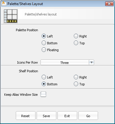
Your interface changes take place immediately, and are stored for the next time you launch Alias.
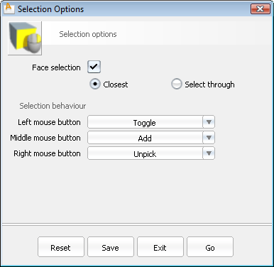
Selection Options by clicking its .
The Selection Options window opens.
If you have not already viewed the Essentials Skills videos, do so now (in Alias, select HelpLearning Movies).
Beyond the interface tools shown in these videos, these are two valuable tools to increase your comfort and speed when working in Alias:
Marking menus are a fast way to access frequently used tools and commands directly within any view or window.
Hold down the  and
and  keys and press either the
  ,
,  , or
, or  mouse buttons to access a floating, radial menu of commands around your mouse cursor. This menu persists until you release
the mouse button.
mouse buttons to access a floating, radial menu of commands around your mouse cursor. This menu persists until you release
the mouse button.
You select the tools and menu items by releasing the mouse button over them.
Access the options window for a tool by releasing the mouse button over the located to the right of the tool or menu name.
and and holding the appropriate mouse button) is enough to activate the tool. This technique is much faster than accessing frequently
used tools by finding and clicking on their icon or menu item.
The ViewCube and NavBar are familiar elements in many Autodesk applications. They allow quick navigation around the scene.
The ViewCube is visible at all times, but is dimmed when the mouse is not near it. The NavBar only appears when you press
the  and (Windows) or
  and (Mac) keys.
For information on using the ViewCube and NavBar, see the Alias Help.
This setting displays the view with natural perspective when you click any corner or edge of the ViewCube or tumble around the model, but reverts to traditional orthographic views when you click a face of the ViewCube.
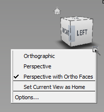
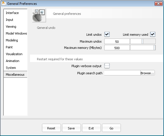
You can toggle the ViewCube on or off in the Preferences General Preferences option box (Viewing section).
Now that you have set up general application preferences and viewing conventions, you can create a file with appropriate settings for the size and eventual output of the model.
Define Construction Options for the file
Construction Options insure that modeling is done with the tolerances and units that other applications expect when refining the engineering of our design. These settings do not generally constrain the creative process, but using a preset now allows for later modification and expansion in Autodesk Inventor.
The finished model for this tutorial is approximately 400 mm in the longest dimension. This is much smaller than the default grid layout in Alias.
Grid Preset . This is the menu flow visible by -clicking on the Palette tab.


To assist the modeling process, a sketch is often used as a reference. The sketches for this tutorial are provided on the Alias wiki. You will import Top, Left, and Back view sketches into your scene. A Perspective sketch is included to provide a look at the overall design.
Create a canvas plane for the top view image
All WindowsAll Windows to show the Left, Top, Back, and Perspective views, if they are not already visible.
New Canvas
to show the Left, Top, Back, and Perspective views, if they are not already visible.
New Canvas .
.
Pixels Width to 1680 and Height to 640 to match the resolution of the image you are importing.
mm Width to 420 and Height to 420 to match the physical size of the new object.

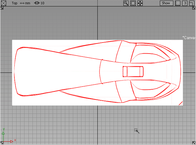
Add the top view image to the canvas
ImportCanvas Image .
.
The image is centered in your Top view canvas.
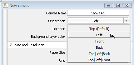
Create a canvas plane and add the left view image
New Canvas and set the following options:
Set the Orientation to the Left view.
Pixels Width to 1680 and Height to 640 to match the resolution of the image you are importing.
mm Width to 420 and Height to 420 to match the physical size of the new object.
ImportCanvas Image and choose VacuumLeft.jpg.
Move the canvases so that vacuum design rests on the XY plane
In the Left and Back views, notice that the canvas is centered on the origin as in the Top view. The vacuum design should be resting on the XY plane in the positive Z direction.
 and drag to move both canvases along the Z axis until the bottom of the sketch is aligned with the darker "origin" line.

 and keys, and click with the to bring up the Pick marking menu.

Set image canvas display preferences
To make it easier to see the geometry and other elements in the scene, dim the Canvases and place them in a new layer that prevents picking the canvases during modeling.
New .
.
A new layer appears in the Layer Bar below the prompt line.
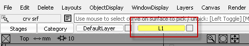
No objects are in this layer, since the image reference canvases were created on the DefaultLayer. It is a good idea to create new layers before creating the geometry or objects to go on them to avoid objects being left on the DefaultLayer. The Default Layer allows instant organization from a new scene, but it cannot be hidden or made into a reference layer.
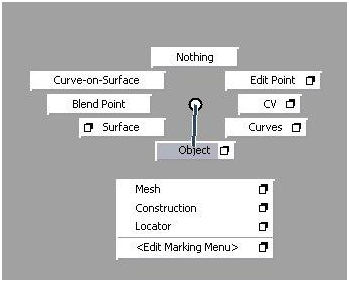
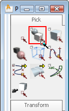
Pick Object tool (hold + + to show the Pick marking menu, then drag down to Object).
Click and drag a selection box around all three canvases in the scene. They are highlighted in white to indicate they are
selected.
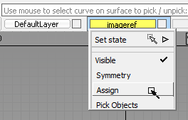
-click on the imageref layer in the Layer Bar to show its controls.
-click again on the imageref layer and choose the submenu item Set stateReference.
tool (hold + + to show the Pick marking menu, then drag down to Object).
Click and drag a selection box around all three canvases in the scene. They are highlighted in white to indicate they are
selected.
-click on the imageref layer in the Layer Bar to show its controls.
-click again on the imageref layer and choose the submenu item Set stateReference.
The layer appears brown in the Layer Bar, and the reference image canvases are unpicked. They can no longer be picked interactively like other objects in the scene.
To dim the images in the scene, reduce the opacity of the canvases.
+ + to show the View marking menu.

The three canvas planes are shown as layers with control options.
Window Sync is checked. If not, select the menu item to toggle it.
With these preferences and reference images in the scene, it is a good time to save the file for the later work.
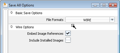
Save As to open the Save All Options window.
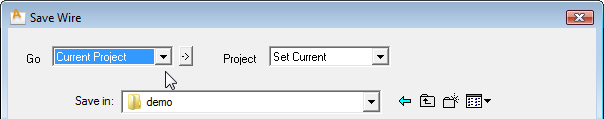
These project directories for various elements have been automatically created in your User Documents folder.
Each time after this that you use Save or Save As, the file goes into this directory.
Now that the scene is set up, proceed to the next lesson (Getting Started) to create and modify geometry.


 to start a new, empty document, and confirm the deletion of all objects, shaders, views, and actions.
 .
.