A common way to combine NURBS surfaces is to intersect the surfaces, then trim them where the two surfaces cross each other. This is the approach you will take with the upper and lower surfaces of the vacuum cleaner.
First, you will intersect the surfaces. When you intersect surfaces, you create curves-on-surface, which are lines that are created on the surfaces where the surfaces intersect. You will then trim the intersecting surfaces along the curves-on-surface, so the unnecessary surface areas are discarded, and only the necessary surface areas remain.
Opening the tutorial file (optional)
If you successfully completed Part 1, you can proceed directly to the next step, Intersecting the upper and lower surfaces.

If you were not successful in part 1, open the file called vacuum_part2.wire, located in the wire directory of the CourseWare project. This file contains the completed model from Part 1.

Watch Part 2 of the tutorial.
Intersecting the upper and lower surfaces
Now, you will intersect the upper and lower surfaces to create the body shape.

 . This tool creates the curves-on-surface
that are used to trim the surfaces.
. This tool creates the curves-on-surface
that are used to trim the surfaces.
Use
the  to click the upper surface
to select it.
to click the upper surface
to select it.

The surface is highlighted and a Go box appears in the lower right corner of the view.
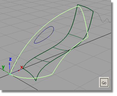
Click the Go box to select the first surface to be intersected.

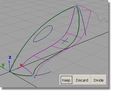
The surface is highlighted in pink.
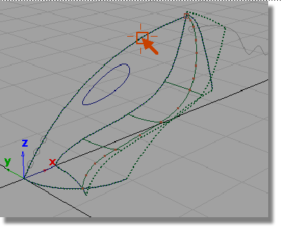
Click the lower surface to intersect it with the upper surface.

The surfaces are intersected. Two curves-on-surface are created, one on each surface.

By default, the Intersect tool creates a curve-on-surface on each surface so each surface can be trimmed.
Both surfaces are now drawn with a dotted outline to indicate that each has a curve-on-surface.
 .
.

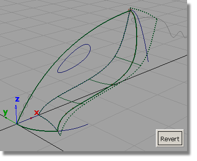
The highlighted curves that appear are the two curves-on-surface. It looks as though there is only one curve-on-surface, but in fact there are two in the same location, one on the upper surface, and one on the lower surface.

 to unpick the curves-on-surface.
Now, you will trim off the excess from the upper and lower surfaces.
 button that appears at the
bottom right corner of the screen.
button that appears at the
bottom right corner of the screen.
 .
.
Pick the upper surface.
Shift select to select surfaces or click to select REGIONS.
The last option allows you to trim away the excess parts of the surface, so this is the prompt you will respond to.
Click any part of the upper surface on the inside part that you want to keep.

The Trim tool places an indicator where you clicked and an option box appears in the bottom right corner of the view.

The upper surface is trimmed.


Next, you will create a planar surface across the mouth of the nozzle, to complete the exterior shape of the vacuum body.
 tool.
tool.
You are prompted to select a curve.

The curve is selected and a Go button appears in the bottom right corner of the view.
You are prompted to select another curve.

The curve is selected, and you are prompted to select another curve.

The curve is selected. The three curves form a closed region within which the planar surface will be created.

The surface is created and highlighted in pale yellow.
to deselect the planar surface.

 to save the current scene.


