In this section, you will use the Square, Skin, and Align tools to create the basic shape of the shower gel bottle.
You will build the front half of the bottle, which will later be mirrored to complete the design. You will create a smooth connection between both halves by controlling the implied tangent continuity across the center line.
When you create the shoulder surface, you will blend it smoothly to the main bottle surface using tangent continuity.

Watch Part 1 of the tutorial.
The tutorial file has curves for building the shower gel bottle.
 to open the File Browser.
(For information on how to open a file, see Opening the tutorial file.)


The file is opened.
The main bottle curves are visible and placed on a layer named Curves.
Other curves are on layers that are not currently visible; you will use these later in the tutorial.
Setting the Construction Tolerances
Before you start to create your model, you will choose the construction tolerances you want to work to.
 .
.
The Construction Preset is set to User Defined. While this is suitable for rapid concept development, a more accurate setting will be needed for data transfer to a CAD or Rapid Prototyping system.

To see what tolerances you will be working to, open the tolerances section of the Construction Options window.

Creating the Main Bottle Surface
You will start by creating the main bottle shape using a Square surface.


 .
.

In the Square option window, the four boundaries of the square are listed.
For boundaries, 2 and 4 change the continuity option to Fixed. This ensures that the square surface accurately matches the curves.
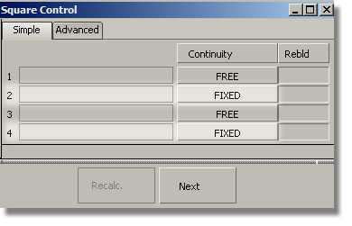
For boundaries 1 and 3, change the Continuity option to Implied Tangent. The Implied Tangent option ensures the surfaces will align smoothly across the center line.

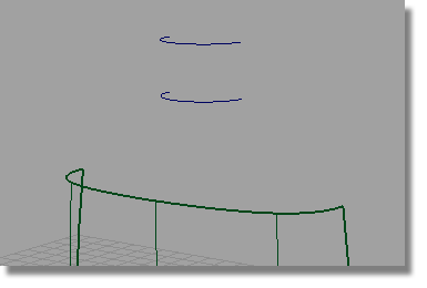
You are prompted to select the four boundary curves. Click the curves in the order shown.
When the fourth curve is selected the square surface is created.

 and, when prompted, select
the two neck curves to create the neck surface.
and, when prompted, select
the two neck curves to create the neck surface.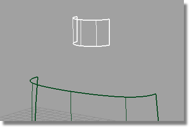

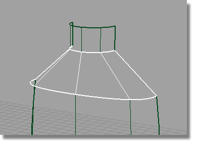
The shoulder surface needs to blend smoothly from the main body surface.
First, you will create the shoulder as a simple skin surface from the body to the neck. You will then create continuity between the shoulder and body, using the Align tool.
It is useful to understand how the Align tool creates the desired continuity, and you can see this by observing how the CVs and Hulls change as the Align tool is applied.
First, create the shoulder surface with positional continuity.
tool.
Now, you will use the Align tool to modify the shoulder surface, making it Tangent to the body surface.
First, delete the Construction History of the shoulder skin, to allow it to be modified.
 and answer Yes when
prompted.
and answer Yes when
prompted.

 . Double-click the Align icon
to open the option window. Set Continuity to Tangent.
. Double-click the Align icon
to open the option window. Set Continuity to Tangent.
You are prompted to select the boundary of the surface to be aligned (the input). This is the skin surface you created for the shoulder.

The selected edge is highlighted and labeled as “Input”.
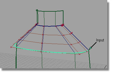
You are prompted to select the object to align to (the master).
The top edge of the body surface is automatically selected.
The CVs of the shoulder surface are modified to align the shoulder to the bottle surface with tangent continuity, as indicated by the T on the green indicator.


Now, you will modify the character of the shoulder blend by moving and scaling the CVs and Hulls.

 to deselect the surface.
 .
.
In the Back window, select the hull of the second row of CVs from the top by clicking the red hull line.

 to create a smooth shoulder
shape.
to create a smooth shoulder
shape.

to refine the shoulder shape.

 click the hull of the third
row of CVs and drag upwards to sharpen the shoulder profile.
click the hull of the third
row of CVs and drag upwards to sharpen the shoulder profile.
Continue to adjust the vertical position of the hulls until you are happy with the design.
to deselect the CVs.

Now you will save the scene as a new file.
For information on creating the Lessons project, or saving your work, see Saving your work in a Windows environment or Saving your work in a Mac OS X environment.


