To build from four boundary curves with continuity
Create surfaces by blending four boundary curves (or curve segments), while maintaining continuity with adjacent surfaces.
To create a new surface by blending four boundary curves (or curve segments)
 icon, or choose Surfaces
> Boundary Surfaces > Square ❒ from the tool palette.
icon, or choose Surfaces
> Boundary Surfaces > Square ❒ from the tool palette.
The Square Control window appears.
or

Click a point on the curve (to use as a corner)
by holding down either the  (Windows) or
  (Mac) key or the and
  (Windows) or and
  (Mac) keys.
or
Click a grid point (to
use as a corner) by holding down the (Windows) or (Mac) key.


To use the tangent angle manipulator

This manipulator appears when you set an edge to Tangent Angle in the Square Control window (see below).
To edit the construction history of a Square surface
icon, or choose Surfaces
> Boundary Surfaces > Square from the tool palette.
The Square Control window appears.

In these cases, the Square tool will guess which segment to use. If it guesses incorrectly, detach the ambiguous curve to create two separate, non-ambiguous curves.
If you have continuity constraints on all edges, the constraints may sometimes conflict and fail.
The Influence sliders are found in the Square Control window when Blend Type is Cubic.
When you specify the
four corners of a Square surface, you must specify
the first corner using a snap mode (that is, holding down either
the (Windows) or  (Mac) key, the (Windows) or (Mac) key, or the Ctrl and (Windows) or and (Mac) keys). However, you
can specify the remaining corners with or without using a snap mode.
(Mac) key, the (Windows) or (Mac) key, or the Ctrl and (Windows) or and (Mac) keys). However, you
can specify the remaining corners with or without using a snap mode.
 settings.
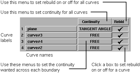
The Continuity Table displays one row for each boundary curve involved in the Square operation.
Free Boundary – This edge is free to move if required by another edge’s continuity or by the Influence sliders (see below). This is the default.
Fixed Boundary – Keep this edge exactly like the boundary curve that created it. In other words, do not let the edge move as with the Free option. This is equivalent to positional continuity.
Implied Tangent – Try to keep tangency with an implied surface that shares this edge. The implied surface is the surface that would be created by mirroring the new surface. (The way the Square tool tries to keep tangency with an implied surface is by blending the slopes of the boundary curves.)
This is a powerful feature. It lets you model one half of a symmetrical surface (such as a car body), and maintain continuity at the seam. When you duplicate the surface to create the other half, the seam will already be continuous. For this to work across a symmetry plane, you must make sure the ends of the curves are tangent across the symmetry plane (that is, the tangents are perpendicular to the symmetry plane).
Tangent Angle – Try to keep tangency at an angle with a surface that shares this edge.
Tangent – Try to keep tangency with a surface that shares this edge.
Curvature – Try to keep curvature continuity with a surface that shares this edge.
Linear – Create the new surface by blending the free CVs (CVs not controlled by the continuity options) of the four boundary curves.
Cubic – Create the new surface by interpolating the boundaries (as in Linear), plus the tangent and curvature ribbons. The interpolation is cubic (if only tangent continuity is needed) or quintic (if curvature continuity is needed).
Depending on how much the tangent and curvature ribbons change, Cubic blends can be much wavier than Linear blends.
These sliders control the point of equal influence of opposite boundaries (in other words, the midpoint of the blend between opposite boundaries): that is, between 1 and 3, and between 2 and 4. Values can effectively range from 0.17 to 0.83.
Changing the surface using the Boundary Blend sliders is slow, because continuity must be recalculated. For very complex surfaces, or when using Curvature or Tangent Angle continuity, you may want to turn off the Auto Recalc option.
These sliders control how much each set of boundary curves influences the new surface.
They only appear when Blend Type is Cubic.
For example, if you set the 2-4 Influence slider to 0.0, the new surface will mostly blend between edges 1 and 3, and will have little of the shape of edges 2 and 4.
Changing the surface using the Influence sliders is much faster than with the Boundary Blend sliders, because continuity is not affected.
Turn on this option to open the Explicit Control Options section that allows you to explicitly specify the degree and number of spans of the surface in both the U and V direction.
The following two options only appear if Explicit Control is turned off.
Maximum number of spans the Square tool can insert on each edge of the new surface as it tries to achieve continuity.
If the Square tool cannot achieve tangency without inserting more than the allowed number of spans, it displays an error in the prompt line.
Max. New Spans is not available when Explicit Control is turned on.
On – Insert extra edit points at the midpoint of the span with the largest continuity deviation. This is the default, and results in a better distribution of the isoparametric curves.
Off – Insert extra edit points at the location of the largest continuity deviation.
Insert at Midpoint is not available when Explicit Control is turned on.
Save the history of the new surface for later editing. If you turn Create History on, you can modify the curves that were used to create the surface, and the surface will update.
Update the new surface automatically as you change the values in the Square Control window.
Display the surface continuity
locator at the boundaries between the square surface and adjacent
surfaces. The locator is persistent and will remain after you exit
the Square tool. To remove it,
use Pick > Locator  to pick the locator, then
select Delete > Delete Active
to pick the locator, then
select Delete > Delete Active  , or toggle the checkmark
off when entering Square again.
, or toggle the checkmark
off when entering Square again.


