
Watch the tutorial.


The file is displayed.
 . This will hide all tools
not needed for visualization or rendering work.
. This will hide all tools
not needed for visualization or rendering work.
 . This opens up a frame in
the window containing frequently used tools for the visualization
process. Between the menus, marking menus, and control panel, you
have all the tools you need to work on an image at your fingertips.
. This opens up a frame in
the window containing frequently used tools for the visualization
process. Between the menus, marking menus, and control panel, you
have all the tools you need to work on an image at your fingertips.
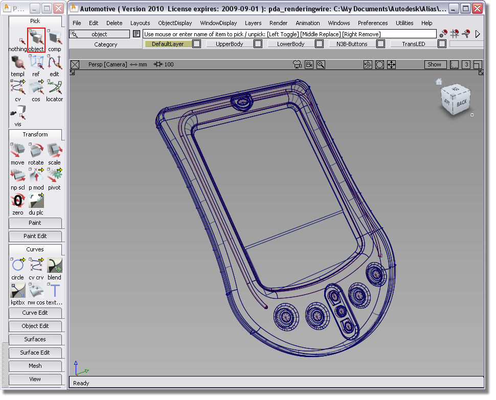
Your Alias window should look like the following illustration.

As a first step in the
journey to understanding rendering, you will use shaded mode. This tool
provides a fast colored and shaded reference of a model in a modeling
window. You can also enable textures, shadows, reflections, and
more. For more information about all the functionality of this mode,
see WindowDisplay > Hardware Shade  .
.
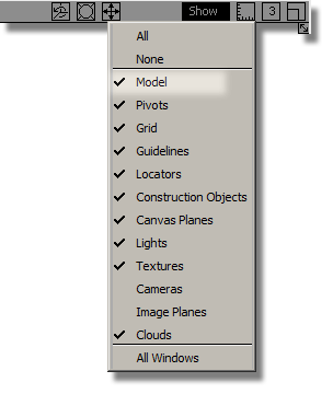
❒ to open the Hardware Shade window.

Tumble about to get a good view of the model.
Click Shade off.
without opening the option
window. It applies the Shade settings to the window, without having
to open the window.
You will notice that color and surfaces have been applied to the wire frame of the personal digital assistant (PDA). These colors and textures are created by a number of shaders, which are visible in the Resident Shaders tab of the Visualization panel.
again.
We will take a quick look at shaders, and the tools you can use to change them.
After you have created wire frames, such as those supplied in the PDA model, you will want to see them wrapped in surfaces that can then be transformed into rendered images. To make the rendered images as striking and realistic as possible, you need to apply shaders and textures to your objects.
Alias uses shaders to define the appearance of your objects, so they look as if they were created with real materials. Textures can also be applied to the shaders to create more sophisticated visual effects. As you will discover in later tutorials, you can even add special effects to shaders to make them appear semi-transparent or to give them a sense of 3D relief.
The visualization panel provides you with fast access to libraries of shaders and to the most-used capabilities of the multi-lister.
In the previous section
of this tutorial, when you switched to shaded mode via WindowDisplay > Hardware Shade , you were viewing a shader
we already applied to the model. Let’s now look at the shaders in
the Visualization panel.


All of these spheres are shaders that are assigned to different parts of the PDA. To see which sphere is assigned to which part of the PDA, click a sphere.

This tool picks objects by the current shader. You can choose each shader and click this tool to see which shaders are assigned to what parts of the model by looking in the Perspective view after you have clicked this tool.
You can also modify some attributes of shaders in the visualization panel.
You will see that the button at the top of the PDA is highlighted.
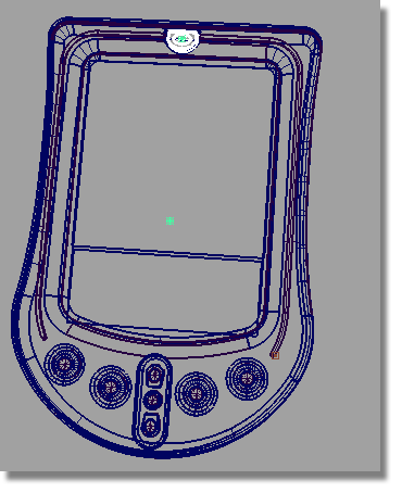

to see the model with an
orange button.

In addition to editing shaders, you can also create new shaders by copying and modifying existing shaders, or import new shaders to your model from a library by double-clicking a shader in the library.
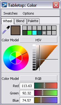
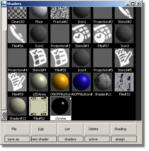
The Multi-lister is the full interface you use to create, edit, manage, and display shaders, textures, lights, and the environment. You also use the Multi-lister to access the Control Window and the Color Editor.
To open shaders in the Multi-lister
 over the background of the
multi-lister, and choosing either Large Icons or Small Icons. The
images in this tutorial show small icons.
over the background of the
multi-lister, and choosing either Large Icons or Small Icons. The
images in this tutorial show small icons.
The Chrome shader was applied to the PDA case. Next, you will edit it to make it reflect an environment.
The Chrome editor is opened. Notice there are two tabs: Software and Hardware. You can use either tab for this exercise. The Hardware tab shows a subset of the fields available on the Software tab: these fields are used in WindowDisplay > Hardware Shade.

This opens the texture editor for the Chrome reflection.

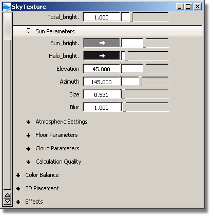
This opens the SkyTexture editor.
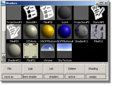
The Shaders window is updated to reflect the changes. Note how the Chrome shader wears the Sky texture.
To see the effect of your changes, look at the shaded model in the perspective window.

Now it is reflecting the sky.


