 Command entry:Select an object.
  Right-click quad menu Transform (lower-right) quadrant Wire Parameters Choose parameters to wire.
Command entry:Select an object.
Right-click quad menu Transform (lower-right) quadrant Wire Parameters Choose parameters to wire.
Command entry:Select an object.  Modify panel Right-click text box portion of animatable parameter spinner. Choose Show In Parameter Wire dialog.
Command entry:Select an object with a wired parameter. Modify panel Right-click text box portion of a two-way-wired parameter Edit Wire
Modify panel Right-click text box portion of animatable parameter spinner. Choose Show In Parameter Wire dialog.
Command entry:Select an object with a wired parameter. Modify panel Right-click text box portion of a two-way-wired parameter Edit Wire
The Parameter Wiring dialog allows you to define the relationships for Wire Parameters. In this dialog, you can create new one and two-way control relationships between object parameters, edit existing relationships, and create or edit expressions which define the parameter relationships.
Only parameters that can be animated can be wired. Sub-objects, such as vertices, must be animated before they can be wired.
Parameter wires can be used to establish connections from Manipulators and Custom Attributes to objects, materials, and modifiers.
Example: To use an expression with wire parameters:
Wire Parameters.
Length.
A rubber-band dashed line now connects the box and the mouse cursor.
Position Z Position from the pop-up menu.
The position of the sphere and the length of the box are now wired.
Notice that as the sphere moves in the viewport, the length of the box changes. Using abs() ensures that the box never has a negative length.
To control several slave parameters from one master parameter:
You can repeat this cycle to set up as many slaves as you want. The result is a “fan” of parameter wires, so that you can control all of the slave parameters at once as you change the master parameter.
To create a chain of wired parameters:
You can repeat this cycle, continuing to alternate slaves to masters as many times as you like. The result is a “daisy chain” of parameter wires, so that as you modify the original master parameter, each slave parameter maintains a constant relationship with the next in a line of parameters.
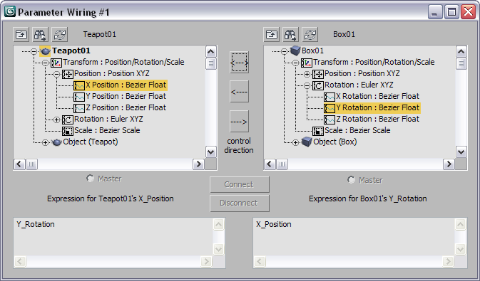
The dialog presents two tree views that display the animatable parameters of all of the visible objects in the scene. The names of the currently selected objects appear at the top. The tree views display the objects in the scene and allow you to select and wire all of the animatable parameters of the objects in the scene and the scene itself.
The tree views are color-coded to show existing wiring. A parameter with a wire controller assigned to it (either as the member of a two-way pair or as the slave in a one-way wire) displays in red. When a wire-controlled parameter is selected, all of the parameters wired directly to it are displayed in green text in the other Tree View. In either case, if the parameter is inside a track that is not expanded, the enclosing track will display in red or green, so you can expand the tracks to find the wires.
The buttons above the tree views are:
 Show All Tracks
 Find Next Parameter
 Refresh Tree View Content to Selected Node
The Parameter Wiring dialog provides three direction-control buttons between the tree views. You can choose only one of these at a time. These buttons determine the direction of control, either one-way or two-way:
 Two-way connection [two-headed arrow]Click this to link both parameters to each other, so that changing either parameter affects the other.
 One-way connection: right parameter controls left parameter [left arrow]The right parameter controls the left parameter.
 One-way connection: left parameter controls right parameter [right arrow]The left parameter controls the right parameter.
 Connect/Update
 Disconnect
The Parameter Wire system provides a way for the pair of wired parameters to be animated as a single system. It does this by setting up a subcontroller on one of the parameters; any animation on this controller drives the Wire Controller pair. The animation subcontroller is always assigned to the master parameter of the wired pair. By default, this is the parameter that is clicked first in the wiring interaction. The master parameter can also be designated with the Master radio buttons beneath the tree views.
The animation subcontroller appears as a nested track inside the master parameter’s track in Track View and its values directly drive and match the master parameter values. If the subcontroller is keyframable (which is the default when a two-way wiring is first established) it can be keyframed by adjustments of either of the wired parameters. This means that if you keyframe the wired pair by adjusting the non-master parameter, the values keyframed into the animation subcontroller are derived from the master parameter transfer expression. Since the wired pair can be animated through either parameter, the choice of master parameter is essentially just a convention.
Underneath the parameter trees are the transfer expression text boxes. These expressions determine how changes to each parameter affect the other and are usually inverses of one another.
For more information on expression syntax, see the topic “Script Controllers” in the MAXScript Help.
When the parameters are first wired, the default expressions are simple 1-to-1 links between the parameters. These expressions can be edited into any valid script fragment that will yield a result of the correct type for its parameter. For example, if you link a parameter such as height (which contains a float value) to a parameter such as position (which contains a point3 value), your expressions must include conversions that produce the same output value type.
For one-way wires, the Expression box for the controlling parameter is unavailable, since there is no Wire controller assigned to it.
For two-way wiring, both transfer expression text boxes will be enabled. It is possible for the user to supply transfer expressions for the two parameters that are not inverses of one another, but this is of course discouraged, since the relationship of the parameters will be different depending on which one is changed first.


