A Bones system is a jointed, hierarchical linkage of bone objects that can be used to animate other objects or hierarchies.
Bones are especially useful for animating character models that have a continuous skin mesh. You can animate bones with forward or inverse kinematics. For inverse kinematics, bones can use any of the available IK solvers, or through Interactive or applied IK.
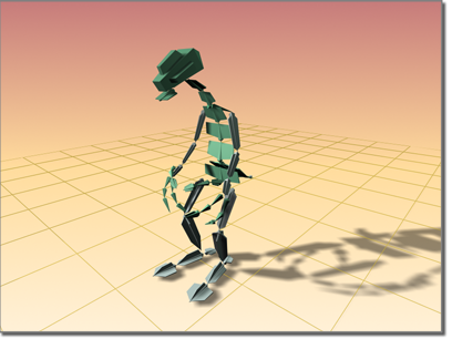
Dinosaur character modeled using bones
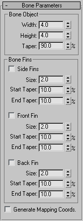
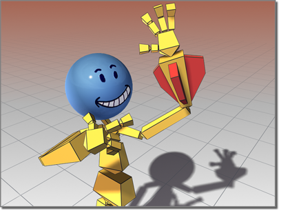
Bones are renderable objects. They have several parameters, such as taper and fins, that can be used to define the shape the bone represents. The fins make it easier to see how the bone is rotating.
For animation, it is very important that you understand the structure of a bone object. The bone's geometry is distinct from its link. Each link has a pivot point at its base. The bone can rotate about this pivot point. When you move a child bone, you are really rotating its parent bone.
It might be useful to think of bones as joints, because it is their pivot placements that matter, more than the actual bone geometry. Think of the geometry as a visual aid that is drawn lengthwise from the pivot point to the bone's child object. The child object is usually another bone.
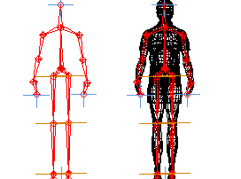
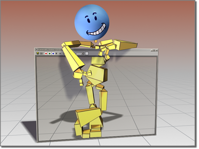
Bones system seen alone and inside a wireframe model
Any hierarchy can display itself as a bone structure (see Using Objects as Bones), by simply turning on Bone On in the Bone Editing Tools rollout.
You start creating bones by clicking the Create Bones button on the Bone Editing Tools rollout, or by clicking the Bones button in the Systems category on the Create panel.
To create bones, do the following.
This creates a small “nub” bone at the end of the hierarchy, which is used when assigning an IK chain. If you are not going to assign an IK chain to the hierarchy, you can delete the small nub bone.
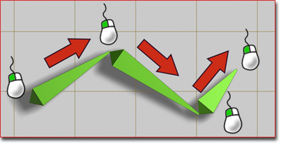
Creating a simple chain of three bones
3ds Max lets you create a branching hierarchy of bones. To create a branching hierarchy, such as legs branching from a pelvis, do the following:
Assigning IK Controllers to Bones
By default, bones are not assigned inverse kinematics (IK). Assigning an IK solver can be done in one of two ways. Typically, you create a bone hierarchy, then manually assign an IK solver. This allows for very precise control over where IK chains are defined.
The other way to assign an IK solver is more automatic. When you create bones, choose IK solver from the list in the IK Chain Assignment rollout, and then turn on Assign To Children. When you exit bone creation, the chosen IK solver is automatically applied to the hierarchy. The solver extends from the first bone in the hierarchy to the last.
For more information about IK, see Introduction to Inverse Kinematics.
By default, bones are assigned the color specified for Bones in the Colors panel of the Customize User Interface dialog. Choose Object as the Element and then choose Bones in the list. You can change the color of individual bones by selecting the bone, clicking the active color swatch next to the bone’s name in the Create panel or Modify panel, and then selecting a color in the Object Color dialog.
You can also use the Bone Tools to assign bone colors, or to assign a color gradient to a bone hierarchy.
Fins are visual aids that help you clearly see a bone’s orientation. Fins can also be used to approximate a character's shape. Bones have three sets of fins: side, front, and back. By default, fins are turned off.
Bones can have fins.
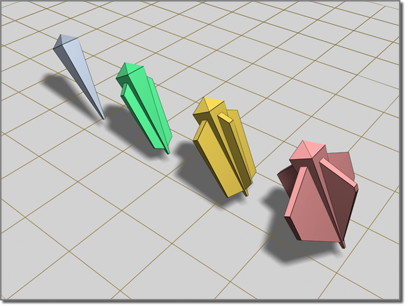
Bones with various fin configurations
Bones can be renderable, though by default, they are not. To make a bone renderable, turn on the Renderable check box in the bone’s Object Properties dialog.
Bones can be renderable.
In addition to visual properties, bones have behavioral properties. The controls for these are located on the Bone Tools floater.
You can use these controls to turn other kinds of objects into bones.
You can apply constraints to bones as long as an IK solver or method is not controlling the bones. If the bones have an assigned IK controller, you can constrain only the root of the hierarchy or chain. However, applying position controllers or constraints to a linked bone can cause undesirable effects, such as breaking of the bone chain.
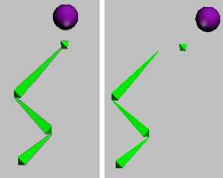
The “nub” bone at the end of the chain has a Spring controller applied to it. The Spring controller is connected to an animated sphere.
Right: The sphere's movement breaks the bone chain.
To avoid this problem, don't apply position controllers directly to child bones. Instead, create an IK chain and apply the controller to the IK chain's end effector.
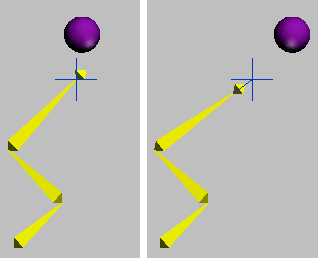
A IK chain has been applied, connecting the end nub to its parent bone. The IK chain's end effector is connected to the ball by a Spring controller.
Right: Now when the sphere moves, the IK chain prevents the bones from breaking.
Constraints and controllers that affect orientation only, such as Orientation or Look At, do not present this problem when applied to child bones.
 Create panel, click
  (Systems). On the Object Type rollout, turn on Bones.
You can also access Create Bones through the Bone Tools rollout.
This creates a joint that is the base of the bone's hierarchy.
3ds Max creates a small “nub” bone at the end of the hierarchy. This bone is used when assigning an IK chain.
The first bone you create is at the top of the hierarchy. The last bone you create is at the bottom. For more about linked objects, see the Hierarchy Panel.
To create a bones hierarchy with an IK solver automatically applied:
Create panel, click (Systems). On the Object Type rollout, turn on Bones.
After the bones are created, the chosen IK solver is applied to them.
To edit the appearance of a bone:
 Modify panel.
To change the length of bones after they’ve been created:
 Bone Tools.
 Select the bone.
Bone Tools.
Select the bone.
Bone Tools.
IK Chain Assignment rollout (creation time only)
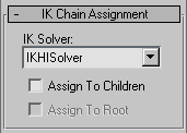
Provides the tools to quickly create a bone chain with an IK solver automatically applied. Also allows for bone creation with no IK solver.
When on, assigns the IK solver named in the IK solver list to all the newly created bones except the first (root) bone. When off, assigns a standard PRS Transform controller to the bones. Default=off.
You can use arbitrary objects such as cylinders or boxes as bones, controlling their animation as if they were bones in a bones system. You can apply an IK solver to the boned objects.
This command opens the Bone Tools floater, which provides functions for working with bones. The floater contains three rollouts, described in the following topics.