Free-form deformations (FFDs) provide a method of deforming an object by adjusting the control points of a lattice. The offset position of the control points to the original lattice source volume causes the distortion of the affected object. The FFD(Box) space warp is a box-shaped lattice FFD object similar to the original FFD modifiers. This FFD is available as both an object modifier and a space warp. For information on the object-modifier version, see FFD (Box/Cylinder) Modifiers.
You create FFD space warps as separate objects similarly to the way you create standard primitives: by dragging the mouse in the viewport. The result is a lattice of control points. The source lattice of an FFD modifier is fitted to the geometry it's assigned to in the stack. This might be a whole object or a sub-object selection of faces or vertices.
Because FFD space warps are separate objects, they carry their own adjustable dimension parameters among the creation parameters.
You can apply object modifiers to space warp objects. For example, you can use the Linked XForm modifier with a space-warp FFD.
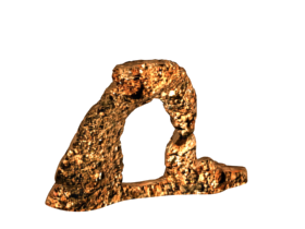
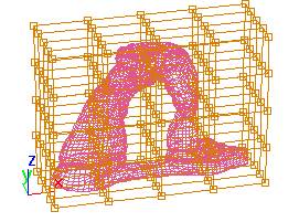
Object and object surrounded by an FFD lattice
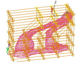
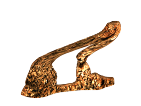
Moving control points in the lattice deforms the object.
To use the FFD(box) space warp:
 Create panel, click
  (Space Warps). Choose Geometric/Deformable from the list, then on the Object Type rollout, click FFD(Box).
 Bind the lattice to the object you want to deform.
If the lattice is to be outside of the object, turn on All Vertices. To affect only those vertices inside the lattice, choose Only In Volume, and position the lattice accordingly.
 modifier stack display, choose Control Points as the sub-object level for FFD(box).
If you're using the Deform group  All Vertices option, once you've distorted the object you can set the Falloff value to adjust how much the lattice affects
the object, based on distance. This is particularly useful if the lattice is animated to approach or move away from the target
object. When Falloff is set to 0, all the vertices are affected, regardless of distance.
All Vertices option, once you've distorted the object you can set the Falloff value to adjust how much the lattice affects
the object, based on distance. This is particularly useful if the lattice is animated to approach or move away from the target
object. When Falloff is set to 0, all the vertices are affected, regardless of distance.
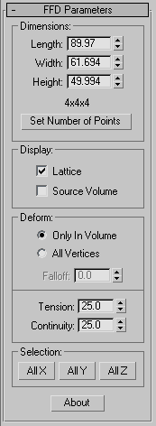
This rollout lets you set the size and resolution of the lattice, and how it displays and deforms.
These options let you adjust the unit dimensions of the source volume, and specify the number of control points in the lattice. Note that the point dimensions are displayed beside the modifier name in the Stack list.
These options provide controls that specify which vertices are affected by the FFD.
All vertices are deformed regardless of whether they lie inside or outside the source volume, depending on the value in the Falloff spinner. The deformation outside the volume is a continuous extrapolation of the deformation inside the volume. The deformation can be extreme for points far away from the source lattice.
This spinner, enabled only when you choose All Vertices, determines the distance from the lattice that the FFD effect will decrease to zero. When this spinner is set to 0, it's effectively turned off, and there is no falloff; that is, all vertices are affected regardless of their distance from the lattice. The units of the Falloff parameter are specified relative to the size of the lattice: A falloff of 1 means that the effect will go to 0 for points that are a lattice width/length/height away from the lattice (depending on which side they are on).
Lets you adjust the tension and continuity of the deformation splines. Although you can't see the splines in an FFD, the lattice and control points represent the structure that controls the splines. As you adjust the control points, you alter the splines (which move through each point). The splines, in turn, deform the geometry of the object. By altering the tension and continuity of the splines, you alter their effect on the object.


