 Command entry: Particle View
  Click Mapping Object in an event or add a Mapping Object operator to the particle system and then click it.
The Mapping Object operator assigns mapping to particles by taking mapping values from one or more reference objects. For every particle, the Mapping Object operator finds the closest point on reference geometry, takes the mapping values and material ID from this point, and then assigns these values to the particle.
If a particle enters the event with mapping already assigned, you can blend the mapping values to avoid a jump in color. Blending can occur either by time or by distance from the reference geometry.
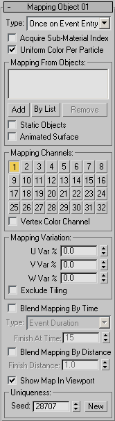
Defines the timing used to acquire and apply the mapping. The options are:
This option takes significantly longer to calculate, as the closest point has to be computed for every particle on every frame. Use this option only when necessary.
When on, the Mapping Object operator assigns the material ID from the nearest face to each particle. If the current event or a previous event has a material operator that uses the reference surface material, this option matches particle coloring to the reference surface. This allows you to blend particles to the reference surface for Multi/Sub-Object materials.
When on, the whole particle gets the same mapping coordinates. As a result, the whole particle is of the same color since the mapping coords are the same across the particle shape. The mapping coordinates are taken from the surface point on the reference geometry nearest the particle pivot point.
When off, a mapping for a particle is a linear approximation of the mapping at the nearest surface point. It's as though mapping from the reference geometry is projected onto the particle. As a result, vertices of a particle have different mapping coordinates, and a texture on a particle represents a patch of texture from the reference geometry. This method is slower because it requires more complex analysis of the reference geometry.
These controls let you assign reference objects, from which particles acquire mapping or material IDs.
When on, the Mapping Object operator updates the surface data at every frame, which is necessary if the reference geometry has surface animation that causes it to change shape. If the object has transform animation only (move, rotate, scale), leave this option off. This option is available only when Static Objects is off.
Clamps mapping values to the 0.0-1.0 range. Variations set by U/V/W Var % can cause mapping values to go below 0.0 or above 1.0. With non-tiling textures, this can cause a visual jump in coloring. When this option is on, if the original mapping value is below 1.0, then adding the variation won’t make it larger than 1.0. If the original mapping is above 0.0, adding the variation won’t make it smaller than 0.0.
By default, the acquired mapping values are assigned to a particle as soon as it enters the event. If particles have been assigned mapping values in a previous event, a visual color jump can result. Use Blend Mapping By Time or Blend Mapping By Distance to cause particles to smoothly blend between previous mapping and mapping assigned by the Mapping Object operator in the current event.
This option defines the timing used for map blending. It is available only when Blend Mapping By Time is on.
Causes particles to blend smoothly between previous and current mapping based on the distance from the reference geometry. At every frame, the operator calculates the distance to the closest surface point. As a particle approaches the reference surface, the blending process occurs. The blending is finished when a particle reaches the Finish Distance in relation to the reference surface. Use this option if particles are directed toward the surface upon entry into the event, as with a Find Target operator.


