The Skin Morph modifier lets you use a bone's rotation to drive a morph; that is, a deformation of the object mesh. Skin Morph is intended for use with Skin or a comparable modifier such as Physique: Add the Skin Morph modifier after the skin-type modifier. You create the morph at the frame in which the effect should be greatest, and then Skin Morph automatically animates the affected vertices into and out of the morph, based on the rotation of the bone that drives the morph.
Skin Morph lets you fine-tune mesh deformation at any frame, using a bone to drive the morph that is fixing a problem area. Often, when you animate a character with bones, you have to create extra bones to handle problem areas such as armpits and the groin. With Skin Morph, instead of adding extra bones, you can simply create a morph and then transform vertices into the exact shape you want. Skin Morph provides an easy way to create muscle bulges and many other effects.
To use Skin Morph (basic usage):
The pose frame contains the initial pose; typically a standing character with arms outstretched and legs apart. This is often frame 0, but it can be any frame, even a negative-numbered one. This is the frame from which the modifier measures delta: the change in the vertex position between this pose and the morph.
For example, bending an arm might cause the inside of the elbow to indent too far, or you might want to add a bulging bicep. In this case, the forearm bone is driving the deformation.
The modifier overlays an orange line along the length of each bone you add.
In the viewport, the orange line representing the bone becomes a thicker yellow line to indicate that this bone will drive the morph.
The modifier adds a morph to the highlighted bone and sets the morph to 100% at this frame, as reflected by the number next to the morph's name in the list.
This temporarily freezes the skin deformation at the current frame.

At the Points sub-object level, you can view and select vertices on the skin mesh. However, you can transform these vertices only when Edit mode is on. The ability to select points when not in Edit mode lets you make the selection when the points are more easily accessible, and then go to the pose to transform them in Edit mode.

Lists all attached bones and their morphs in a hierarchical view. You can expand or contract a bone's morph listing by clicking the + or - box next to its name in the list. The number in parentheses next to the morph name shows its relative influence as a percentage at the current frame.
Highlighting a bone in the list highlights the bone in the viewports as a yellow line, and lets you create a morph for it. Alternatively, you can select the bone in the viewport while the modifier's Points sub-object level is active by clicking the orange line through its center.
Highlighting a morph in the list lets you edit the morph. To change the morph's name, edit the Local Properties rollout  Morph Name field.
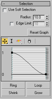
Enables soft selection for editing vertices.
Soft Selection in Skin Morph works much like Soft Selection in other parts of 3ds Max, except that instead of Pinch and Bubble settings you can adjust the graph shape directly, and it uses a Radius setting instead of Falloff to determine the extent of the soft-selection area.
Skin Morph provides a small, full-functioned curve graph for editing soft-selection characteristics globally; it works much like other such graphs in 3ds Max, such as Curve Editor Introduction. The toolbar above the graph offers functions for moving and scaling points on the graph, as well as inserting new ones. The same functions are available by right-clicking the graph: If you right-click a graph point, you can set it to Corner or one of two different Bezier types. If you select a Bezier point, you can reshape the curve by moving its handles.
Expands a vertex selection by first converting the selection to an edge selection, selecting all edges parallel to the selected edges, and then converting the new edge selection back to a vertex selection. Use of Ring requires that a qualifying vertex selection exist; that is, at least two vertices on the same edge.
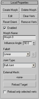
This rollout contains functions for creating and editing individual morphs. The settings, such as Morph Name and Influence Angle, are specific to each morph.
Sets a morph at the current frame for the highlighted bone. Also sets the “pose” for this morph, using the bone's current orientation, and sets the bone to 100%, as shown in the list window hierarchical view. When you edit the morph, the skinned object returns to and stays at this orientation.
When you create a morph, the modifier displays, in orange, all vertices that are part of the current pose (that is, they're offset from the initial pose). Also, the modifier creates a default name for the morph and adds it as a child to the highlighted bone in the list window.
Lets you shape the current morph by transforming vertices. To exit Edit mode, click the Edit button again.
Transforming a vertex in Edit mode creates a morph target. Each transformed vertex moves into the morph target position (or orientation or scale) as the morph value increases to 100.0, and then out of it as the morph value decreases, based on the angle of the bone driving the morph.
Transforming a vertex in Edit mode also changes its color from orange to yellow. This lets you easily see which vertices are part of the current morph.
Choosing Edit places the skinned object at the 100% “pose” orientation for this morph (see Create Morph, above). It also activates the Points sub-object level so you can transform vertices using the standard 3ds Max transform tools.
Sets the morph orientation to current orientation of the bone that controls the morph.
This lets you change the angle at which the morph has its greatest effect. For example, if you create a bulging bicep at frame 120, and later decide that the muscle should be largest at frame 150 instead, go to frame 150, choose the morph in the list box, and then click Reset Orientation.
The angle around the bone's current orientation within which the morph takes place. Default=90.0.
This is an important parameter. Think of the influence angle as a cone around the bone at its orientation when you create the morph. Consider an example in which Influence Angle is set to the default value of 90.0 degrees. If the bone starts its rotation beyond 45 degrees away from the orientation at which the morph was created, the morph has no effect at that time. As the bone moves from 45 degrees away to the morph orientation, the morph increases to its full value. As the bone then rotates away, the morph gradually decreases until, at 45 degrees or more away from the morph orientation, the morph no longer appears.
Determines the rate of change of the morph as the bone moves within the influence angle. Use the drop-down list to choose one of four different falloff types: Linear, Sinual, Fast, or Slow. If you choose Custom Falloff, you can then click the G (for Graph) button and edit the falloff using standard curve-graph controls.
Lets you use a different mesh as a morph target. Click the button (default label=-none-) and then select the target object. The target object should have the same mesh structure as the Skin Morph object. After specifying an external mesh, its name appears on the button.
Using an external mesh makes it easier to set up morph targets in a target mesh that uses a reference pose, rather than the skinned, animated mesh of which sections might be interpenetrating, making it difficult to select the specific vertices to be morphed. In this situation, it's probably best to turn Reload Only Selected Verts.
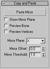
These functions let you copy all morph targets for a specific bone from one side of the object to the other. Indicate the
morphs to copy by highlighting the bone or any of its morphs in the Parameters rollout list box.
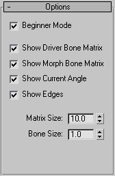
When on, you must use the Create Morph button to create a morph and the Edit button to edit a morph.
When off, you can create and edit morphs on the fly. In this mode, when you select and move vertices at the Points sub-object level, 3ds Max first determines whether a morph exists for the selected bone at 100%; if so, all edits will go to that morph. Otherwise, 3ds Max creates a new morph automatically and applies the edits to that morph.


