Command entry:Select an editable mesh object.
 Modify panel Selection rollout Choose any sub-object level.
The Edit Geometry rollout for Meshes contains most of the controls that let you alter the geometry of the mesh, at either the Object (top) level, or one of the sub-object levels. The controls that the rollout displays can vary, depending on which level is active; if a control is not available for the active level, it might be grayed out, or simply might not appear at all. The descriptions below indicate the levels at which controls are available.
Lets you add sub-objects to a single selected mesh object. Select an object, choose a sub-object level, click Create, and then click to add sub-objects. Available only at the Vertex, Face, Polygon, and Element levels only.
For example, at the Vertex sub-object level, Create lets you add free-floating vertices to the object. The new vertices are placed on the active construction plane.
To create faces at the Face, Polygon, or Element level, click Create. All vertices in the object are highlighted, including isolated vertices left after deleting faces. Click three existing vertices in succession to define the shape of the new face. (The cursor changes to a cross when it is over a vertex that can legally be part of the face.)
You can also create new faces at the Polygon and Element sub-object levels. At the Face and Element sub-object levels, a new face is created after every third click. At the Polygon sub-object level, you can continue clicking as many times as you like to add vertices to the new polygon. To finish drawing a new polygon, click twice, or click again on any existing vertex in the current polygon.
At the Face, Polygon, and Element levels, you can add vertices while Create is on by Shift+clicking in an empty space; these vertices are incorporated into the face or polygon you're creating.
You can start creating faces or polygons in any viewport, but all subsequent clicks must take place in the same viewport.
Lets you attach another object in the scene to the selected mesh. You can attach any type of object, including splines, patch objects, and NURBS surfaces. Attaching a non-mesh object converts it to a mesh. Click the object you want to attach to the currently selected mesh object.
When you attach an object, the materials of the two objects are combined in the following way:
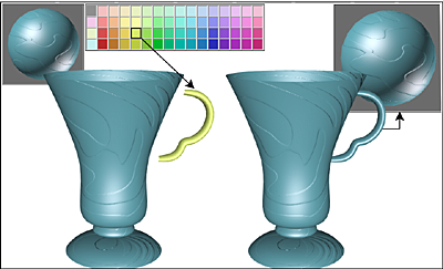
Handle inherits material from the cup it is being attached to.
Upper left: Shaded view of model
Upper right: Wireframe view of model
Lower left: Model with objects attached
Lower right: Subsequent multi/sub-object material
Attach remains active in all sub-object levels, but always applies to objects.
Lets you attach other objects in the scene to the selected mesh. Click to open the Attach List dialog, which works like Select From Scene to let you choose multiple objects to attach.
Detaches the selected sub-object as a separate object or element. All faces attached to the sub-object are detached as well.
A dialog appears, prompting you to enter a name for the new object. The dialog has a Detach As Clone option that copies the faces rather than moving them.
Detached faces leave a hole in the original object when you move them to a new position.
Rotates the edge within its bounding. All mesh objects in 3ds Max are composed of triangular faces, but by default, most polygons are depicted as quadrilaterals, with a hidden edge dividing each quad into two triangles. Turn lets you change the direction in which the hidden edge (or any other) runs, thus affecting how the shape changes when you transform sub-objects directly, or indirectly with a modifier.
Subdivides faces into three smaller faces. This function applies to faces even if you're at the Polygon or Element sub-object level. Click Divide, and then select a face to be divided. Each face is subdivided where you click it. You can click as many faces as you want divided, in sequence. To stop dividing, click Divide again to turn it off, or right-click.
Extrude, Chamfer, and Bevel group
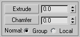
These controls let you extrude edges and faces, chamfer vertices and edges, and bevel faces. Edge extrusion works in a fashion similar to face extrusion. You can apply these tools interactively (by dragging on sub-objects) or numerically (using spinners).
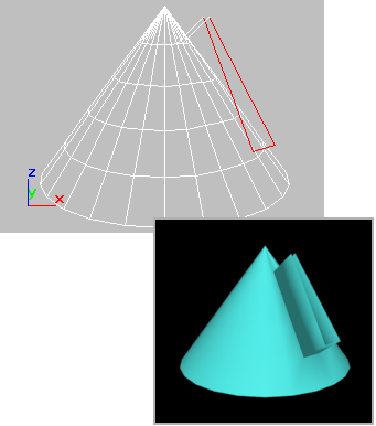
Extruded edges seen in viewport and rendered image
Click this button and then either drag to extrude the selected edges or faces, or adjust the Extrude spinner to perform the extrusion. You can select different sub-objects to extrude while Extrude is active.
The Chamfer controls are available only at the Vertex and Edge sub-object levels. They let you bevel object corners using a chamfer function. You can apply this effect interactively (by dragging vertices) or numerically (using the Chamfer spinner).
Click this button, and then drag vertices or edges in the active object. The Chamfer Amount spinner updates to indicate the chamfer amount as you drag.
If you drag one or more selected vertices or edges, all selected sub-objects are chamfered identically. If you drag an unselected vertex or edge, any selected sub-objects are first deselected.
A chamfer "chops off" the selected sub-objects, creating a new face connecting new points on all visible edges leading to the original sub-object. Chamfer Amount specifies the exact distance from the original vertex along each of these edges. New chamfer faces are created with the material ID of one of the neighboring faces (picked at random) and a smoothing group that is an intersection of all neighboring smoothing groups.
For example, if you chamfer one corner of a box, the single corner vertex is replaced by three vertices moving along the three visible edges that lead to the corner. 3ds Max rearranges and splits the adjacent faces to use these three new vertices, and creates a new triangle at the corner.
Beveling, available only at the Face/Polygon/Element levels, is a second step to extrusion: it lets you scale the faces you have just extruded.
Chamfer box showing extruded face
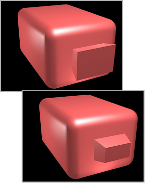
Extruded face beveled in two different directions
You can bevel faces by dragging or by using keyboard/spinner entry.
Click this button, and then drag vertically on any face to extrude it. Release the mouse button and move the mouse vertically to bevel the extrusion. Click to finish.
Lets you subdivide edges with cut and slice tools to create new vertices, edges, and faces. For details, see Cut and Slice (Editable Mesh).
Weld group (Vertex level only)
Enters weld mode, which allows you to select vertices and move them around. While moving, the cursor changes to the Move cursor as usual, but when you position the cursor over an unselected vertex the cursor changes to a + cursor. Release the mouse at that point to weld all selected vertices to the target vertex they were dropped on.
The pixels spinner to the right of the Target button sets the maximum distance in screen pixels between the mouse cursor and the target vertex.
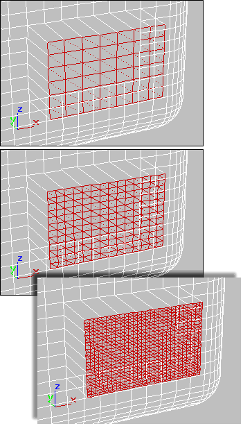
Tessellate group (Face/Polygon/Element levels only)
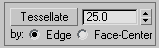
Use these controls to tessellate (subdivide) selected faces. Tessellation is useful for increasing local mesh density while modeling. You can subdivide any selection of faces. Two tessellation methods are available: Edge and Face-Center.
(Active only when Tessellate by Edge is active.) This spinner, to the right of the Tessellate button, lets you increase or decrease the Edge tension value. A negative value pulls vertices inward from their plane, resulting in a concave effect. A positive value pulls vertices outward from their plane, resulting in a rounding effect.
Edge inserts vertices in the middle of each edge and draws three lines connecting those vertices. As a result, four faces
are created out of one face. (To see this at the Polygon or Element sub-object level, turn off Display panel Display Properties rollout Edges Only.)
Face-Center adds a vertex to the center of each face and draws three connecting lines from that vertex to the three original vertices. As a result, three faces are created out of one face.
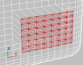
Set of polygons showing Face-Center tessellation
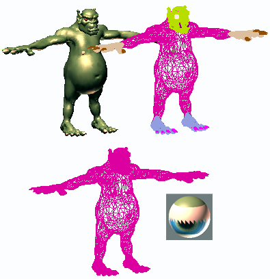
Explode group (Object and Face/Polygon/Element levels only)
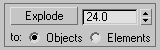
Breaks up the current object into multiple elements or objects based on the angles of its edges. This function is available in Object mode as well as all sub-object levels except Vertex and Edge.
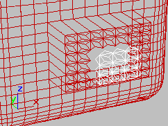
Exploded faces (white) removed from tessellated faces
The angle threshold spinner, to the right of the Explode button, lets you specify the angle between faces below which separation will not occur. For example, all sides of a box are at 90-degree angles to each other. If you set the spinner to 90 or above, exploding the box changes nothing. However, at any setting below 90, the sides all become separate objects or elements.
Aligns all vertices in selected objects or sub-objects to the plane of the active viewport. If a sub-object level is active, this function affects only selected vertices or those belonging to selected sub-objects.
In the case of orthographic viewports, using View Align has the same effect as aligning to the construction grid when the home grid is active. When aligning to a perspective viewport (including camera and light views), the vertices are reoriented to be aligned to a plane that is parallel to the camera’s viewing plane. This plane is perpendicular to the view direction that is closest to the vertices’ average position.
Aligns all vertices in selected objects or sub-objects to the plane of the current view. If a sub-object level is active, function aligns only selected sub-objects.
This function aligns the selected vertices to the current construction plane. The current plane is specified by the active viewport in the case of the home grid. When using a grid object, the current plane is the active grid object.


 Expand the Editable Mesh entry.