The Spline IK solver uses a spline to determine the curvature of a series of bones or other linked objects.
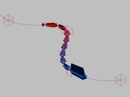
You can move and animate the spline vertices to change the curvature of the spline. Usually, a helper is placed at each vertex to assist in animating the spline. The spline curvature is then passed on to the entire linked structure. The bones themselves do not change shape.
Normally the number of spline vertices and bones are the same, but you can use fewer vertices for easier posing and animating a long multiple-bone structure with just a few nodes, as opposed to animating each bone individually.
Spline IK provides a more flexible animation system than other IK solvers. You can position vertices/helpers anywhere in 3D space, so the linked structure can assume any shape you want to give it.
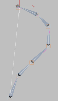
A helper object is automatically placed at each vertex when Spline IK is assigned. Each vertex is linked to its corresponding helper, so a vertex can be moved by moving the helper.
Unlike the HI Solver, the Spline IK system does not use a goal. The positions of helpers/vertices in 3D space is the only factor that determines the shape of the linked structure.
The Spline IK solver can be applied at the time bones are created, or after the bone structure has already been made.
To apply a spline IK solver when bones are created:
 Create panel, click
  (Systems), then click Bones.
By default, Assign To Root is on automatically when you turn on Assign To Children.
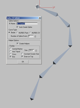
This procedure automatically draws the spline based on your dialog selections and sets up the Spline IK system to work with the spline. 3ds Max automatically assigns a Path constraint to the root bone to constrain it to the helper/vertex at that end of the spline.
To apply a Spline IK solver to an existing bone structure:
 Select the bone or object where you want to the solver to start.
 IK Solvers Spline IK Solver. In the viewport, move the cursor to the bone or object where you want the chain to end and click that bone.
Then move the cursor to the spline and click it.
IK Solvers Spline IK Solver. In the viewport, move the cursor to the bone or object where you want the chain to end and click that bone.
Then move the cursor to the spline and click it. 
The bone structure jumps to the spline and takes its shape, and a helper is created on the spline at each vertex. A Path constraint is automatically assigned to the root bone to constrain it to the helper/vertex at that end of the spline.

To specify a spline after the spline IK solver is applied:
You can also apply a Spline IK solver to an existing bone structure without selecting a spline, then choose the spline later.
Select the bone or object where you want to the solver to start.
IK Solvers Spline IK Solver. In the viewport, move the cursor to the bone or object where you want the chain to end and click that bone.
Then right-click in the viewport to end the IK solver creation without choosing a spline.
 Motion panel. On the Spline IK Solver rollout, click Pick Shape and click the spline.
With this method, the position constraint is not automatically assigned to the root bone, so it must be assigned manually.
Select the root bone. Choose Animation menu Constraints Path Constraint, and then click the spline.
This moves the bone structure to the spline, if they're apart, and creates a Position List controller for the bone with the Path Constraint as the second (active) constraint.
Working with the Spline IK Solver
To use the Spline IK Solver, move the helpers to shape the spline. Do not move the spline. The shape of the spline is determined by the positions of the vertices, so moving the spline itself has no effect on the bone structure. If the spline is moved, it will snap back to the helpers the next time a helper is moved. However, it is recommended that you not move the spline at all.
Once you have finished setting up the spline IK solver, it can be helpful to freeze the spline to avoid accidentally moving it.
Moving helpers changes the shape of the spline. To twist the spline, select the spline IK chain object and go to the Motion panel to change twist angles in the IK Solver Properties rollout.
The Spline IK Solver dialog appears after bone creation if the Spline IK Solver has been selected as the IK solver and Assign To Children is turned on.
When a Spline IK chain is selected, the options on the Motion panel can be used to change the starting and ending bones, and twist angles for the entire linked structure.


