Command entry:
Create panel


(Geometry)
Patch Grids
Quad Patch
Command entry:Create menu
Patch Grids
Quad Patch
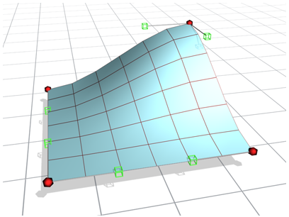
Quad Patch creates a flat grid with a default of 36 visible rectangular facets. A hidden line divides each facet into two
triangular faces for a total of 72 faces.
Procedures
To create a quad patch:
- On the Create panel, activate (Geometry). Choose Patch Grids from the drop-downlist, then on the Object Type rollout, click Quad Patch.
- Drag in any viewport to define the length and width of the patch.
To edit a Quad Patch:
-
 Select a Quad Patch.
- On the Modify panel, right-click Quad Patch in stack view and choose Editable Patch.
The Quad Patch collapses to an Editable Patch.
- On the Editable Patch Selection rollout, click
 (Vertex).
- In any viewport, select a vertex on the patch object, and move the vertex to change the surface topology.
Vertices and vectors can be animated with an Editable Patch modifier.
At the Edge sub-object level, you can add patches along any edge. You can create complex patch models beginning from a single
patch.
Interface
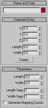
Keyboard Entry rollout
- X/Y/Z
-
- Length
-
- Width
-
- Create
-
Creates a patch based on the XYZ, Length, and Width values.
Parameters rollout
- Length, Width
-
Sets the grid dimensions in current units.
- Length, Width Segments
-
Determines the number of facets along the length and width of the grid. Default=1.
The density of a Quad Patch rises sharply as you increase the segments. A Quad Patch of two segments on a side contains 288
faces. The maximum is 100 segments. High segment values can slow performance.
- Generate Mapping Coordinates
-
Creates map coordinates for applying mapped materials. Default=off.