Command entry:
Tools menu

Camera Match
Command entry: 
Utilities panel
Utilities rollout
Camera Match button
The Camera Match utility uses a bitmap background photo and five or more special "CamPoint" objects to create or modify a
camera so that its position, orientation, and field-of-view matches that of the camera that originally created the photo.
Procedures
The general process to follow in using Camera Match is described in the following procedures.
To use camera matching:
- Load a bitmap as a background for the renderer.
- Load a bitmap as a background for the viewport.
- Identify on the bitmap at least five features that will be used for the match. These should be objects or corners of objects
in the scene that can be identified and tracked. They should remain visually throughout the scene, and should not change their
shape too much or they won’t work.
- Create CameraPoints, which are helper objects found in these locations:
 Create panel
  (Helpers) Camera Match Object Type rollout CamPoint, and Create menu Helpers Camera Point.
You must have accurate measurements of distances between at least five features in your scene, which can’t be all on a single
plane. Try to use points that are distributed throughout the scene rather than features that are all clustered in the front
or back. This will give the most accurate results.
- Position these CameraPoints to correspond to points in your photo. You can use the Transform Type-In to position the points in the correct locations in 3D space.
- Use the Camera Match utility to assign the CameraPoints to pixel locations on the bitmap.
- Choose Create Camera and a camera is created to match the one that took the picture.
If there are errors and the camera cannot be created, readjust the point positions in 3D space, and reassign them to the bitmap.
It’s easy to make a mistake doing either, but once you get it right the match should work.
To establish the bitmap background for the renderer:
- Reset 3ds Max, and enlarge the Perspective viewport to full screen.
- From the Rendering menu. choose Environment.
- In the Common Parameters rollout, under Environment Map, click the gray box marked None. This launches the Material/Map Browser.
- Be sure to set Browse From to New; if it isn’t set already, then choose Bitmap from the list and click OK. The Select Bitmap
Image File dialog appears.
- Navigate and select the appropriate bitmap and then choose Open.
Use Map is turned on automatically.
- Render the viewport to verify that the background appears in the rendering. Press Shift+Q to render.
To establish the bitmap background to display in the viewport:
- Choose Views menu Viewport Background.
This opens the Viewport Background dialog
- In the Background Source group, click Files. This launches the Select Background Image dialog.
- Navigate and select the appropriate bitmap and then choose Open.
- Set Aspect Ratio to Match Bitmap.
- Make sure Display Background is turned on, and then choose OK.
The background appears in the viewport.
NoteYou can click the Use Environment Background button, but then you don’t have the Aspect Ratio controls.
To create CamPoint objects:
- Do one of the following:
- On the Create panel, turn on (Helpers), choose Camera Match from the drop-down list, then on the Object Type rollout, turn on CamPoint.
- Choose Create menu Helpers CamPoint.
- Create your CamPoint objects anywhere in the scene, and reselect each of them to enter their absolute coordinates using the
Transform Type-In.
- Open the Keyboard Entry rollout.
- Enter the coordinates of the first CamPoint object (0,0,0), click the Create button, and then enter the name in the name field.
TipTo use the keyboard, first click in the X field, enter its value, and then press
Tab to move to the next field and enter its value. Continue this until you tab to the Create button, and then press
Enter to create the CamPoint, followed by
Tab to move back to the X field, where you can start again. You can create all the CamPoint objects with default names, and then
use the Select By Name floater (Tools
Selection Floater) to select and rename the six pointers.
- Repeat the above steps for the remaining CamPoint objects.
NoteAn alternative method is to create the CamPoint objects anywhere in the scene, and then reselect each of them and enter their
absolute coordinates using the Transform Type-In.
You now have the CamPoint objects occupying real-world coordinate positions that correspond to the structure in the bitmap
image. The last sequence of steps involves using the Camera Match utility to specify the screen coordinate points, one for
each CamPoint object, and generating a camera position based on the data.
To use the Camera Match utility:
- On the Utilities panel, click the Camera Match button.
The Camera Match utility appears, listing the CamPoint objects.
- Select the first CamPoint object and click the Assign Position button.
- Place the cursor over the corresponding feature in the bitmap and click.
A small, red cross appears.
- If the dot is not in the right position, you can either click again with the mouse or adjust the Input Screen Coordinates
to tweak its position.
- Select the second object in the list, and repeat steps 3 and 4.
- Repeat for all the points. By setting the red crosses, you’ve indicated the X and Y pixel position on the bitmap and correlated
it with each CamPoint as it exists in 3D space.
- Once you have all of the points set, click the Create Camera button.
A camera is created in the scene based on the location of the CamPoint objects and the specifications of the screen coordinates
points.
NoteIf the Current Camera Error reading is greater than five, at least one of your screen coordinate points is placed wrong. Check
each of them, and review the description following step 5. After reassigning the points, select the existing camera and click
the Modify Camera button to recalculate the camera position.
- Press C to switch the Perspective view to that of the new camera.
Interface
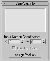
CamPoint Info rollout
- List window
-
Displays a list of the CamPoint helper objects in the scene. You select the CamPoint objects from this list to assign screen
coordinate points. Note that if you select a CamPoint object in the viewport, it‘s highlighted in this list as well.
- Input Screen Coordinates
-
- X/Y
-
Fine-tunes the position of the screen coordinate points in 2D space.
- Use This Point
-
Turns off a specific coordinate point without deleting it. Select the corresponding CamPoint in the list, and then turn off
Use This Point. This feature is typically used for troubleshooting when the Current Camera Error is too high (greater than
five, for example).
- Assign Position
-
Click a location on the viewport bitmap to place a screen coordinate point visually against the background image. The point
you place corresponds to the currently selected CamPoint object. After activating the Assign Position button, select a CamPoint
object from the list, and then click in the viewport at a position on the bitmap background that corresponds with where the
associate CamPoint object should be in the 3D scene. After repeating this process with each CamPoint object in the list, you
can click the Create Camera button to create a camera that matches the placed coordinates with their associate CamPoint objects.
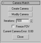
Camera Match rollout
- Create Camera
-
Creates a camera in the scene whose position, orientation, and field of view is based on the current location of the CamPoint
helpers and the assigned screen coordinate points.
- Modify Camera
-
Modifies the position, orientation and FOV of an existing, selected camera based on the CamPoint helpers and assigned screen
coordinate points.
- Iterations
-
Maximum number of iterations used to calculate the camera position. Default is 500, though a stable solution is usually found
in less than 100 iterations.
- Freeze FOV
-
Prevents the FOV (field of view) of the camera from being changed when using the Create Camera or Modify Camera buttons. Use
if the FOV of the camera that took the photograph is known and you want to preserve it.
- Current Camera Error
-
Displays the total error that remains between the placed screen coordinate points, the CamPoint helpers, and the camera position
after the final computation. The calculations involved in the camera match are seldom perfect. A good error range is about
0 to 1.5.
- Close
-
Exits the Camera Match utility.
- CamPoint Helper
CamPoint helper objects are used by the Camera Match utility to reproduce in a camera the same settings (position, roll, and FOV) that were used by a real-world camera to shoot a background
image. This allows you to view your scene from the same perspective as the background image, which is a key step to mixing
computer-generated and photographically-generated images in a single composited shot.