Interface
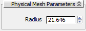
Physical Mesh Parameters rollout (Sphere)
- Radius
-
The radius of the physical mesh sphere primitive. Although the sphere is visualized with multiple vertices in the viewports,
this is an infinitely smooth sphere for the simulation.
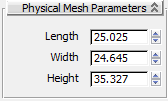
Physical Mesh Parameters rollout (Box)
- Length
-
The size of the box on the local X axis.
- Width
-
The size of the box on the local Y axis.
- Height
-
The size of the box on the local Z axis.
Physical Mesh Parameters rollout (Capsule)
- Radius
-
The radius of the physical mesh capsule primitive. Although the capsule is drawn in the viewports with multiple vertices,
for simulation purposes it is a perfectly smooth shape.
- Height
-
The distance between the rounded ends of the capsule. (A capsule with a height of 0.0 is a sphere.) The end-to-end length
of the capsule is Height + (2 x Radius).
Physical Mesh Parameters rollout (Convex)
The Convex physical mesh is the default type in most cases. This mesh type is automatically generated to add as little computation
overhead as possible to the simulation. If you need to tweak its shape, you can convert it to a Custom mesh with the Convert
To Custom Mesh button on the Physical Meshes rollout.
The mesh responds in real time when you adjust parameters on the rollout, but if you edit the graphical mesh, use Regenerate
From Original to adapt the physical mesh to the modified object.
- # Vertices in Mesh
-
This read-only field shows the actual number of vertices in the generated convex physical mesh. This can vary from the Vertices
setting (see following) depending on the graphical mesh and the other settings on this rollout.
- Inflation
-
The amount to expand the convex mesh outward from the vertex cloud of the graphical mesh (for positive values) or to shrink
it within the graphical mesh (for negative values). Positive values are measured in world units, while negative values are
based on a percentage reduction.
Inflating the convex hull beyond the graphical mesh is a simple way to help prevent interpenetration of fast-moving objects,
but under slow-moving conditions it might cause objects to stand off from one another.
See also the Collision Overlap setting.
- Generate From
-
Choose the method for creating the convex hull:
- Creates a convex physical mesh that wraps fully around the outside of the graphical mesh. This method sometimes creates a
"messy" mesh.
- Reuses a subset of existing vertices from the graphical mesh. This method creates cleaner meshes, but only the vertices themselves
are guaranteed to be outside the graphical mesh. You might need to use a positive Inflation value to keep the convex hull
completely outside the graphical mesh.
- Vertices
-
The number of vertices targeted to be used for the convex hull: between 4 and 256. Using more vertices gives you a better
approximation of the original shape, at a slight cost to simulation speed.
NoteSetting Generate From to Surface might generate more vertices than this value. For the actual number of vertices created,
see the # Vertices In Mesh statistic at the top of the rollout.
- Regenerate from Original
-
Adapts the convex mesh to the current state of the graphical mesh. Use this to re-fit the physical mesh to the graphical mesh
after editing the latter object in such a way that is shape changes. Examples might involve transforming sub-objects or scaling
the object.
Physical Mesh Parameters rollout (Composite)
The Composite mesh type lets you represent a concave rigid body as a series of automatically generated convex hulls. Creating
the hulls can take a long time, depending on the resolution of the graphical mesh, so it is necessary click the Generate button
to generate the composite hulls. The resulting hull and vertex count is displayed at the bottom of the rollout so that you
can evaluate the potential performance impact of the (possibly numerous) convex hulls.
Following are descriptions of the Composite Mesh parameters. After changing any of these settings, click Generate for the
change to take effect.
- Max Vertices
-
The maximum number of vertices to use for each convex hull. Using more vertices gives you a better approximation of the original
shape, at a slight cost to simulation speed.
- Split Levels
-
The maximum partition depth (the number of binary-space partition splits) to use for the composite mesh. Using more split
levels yields a better approximation of the original shape, at a significant cost to simulation speed.
NoteThis parameter results in a maximum of "2 ^ (split levels)" hulls being generated, thus each increment increases the convex
hulls by a factor of 2. However, the actual number of hulls might be far less, depending on the settings for Size Difference,
Shrink Wrap, and Granularity.
- Inflation
-
The amount to expand the convex hull from the vertex cloud of the graphical mesh (for positive values) or to shrink it within
the graphical mesh (for negative values). Positive values are measured in world units, while negative values are based on
a percentage reduction. Inflating the convex hull beyond the graphical mesh is a simple way to help prevent interpenetration
of fast-moving objects, but under slow-moving conditions can cause objects to stand off from one another.
See also the Collision Overlap setting.
- Size Difference
-
The percentage of volume-split threshold for each piece of convex hull, relative to the volume of the entire object.
A high Size Difference value provides a better approximation of the original shape because it enables increased size variation
for the convex hulls. This can lead to a greater number of convex hulls being created, resulting in a cost to simulation speed
as well.
A low Size Difference value results in the creation of fewer hulls of similar size, thus improving the simulation speed at
the cost of precision.
- Shrink Wrap
-
The percentage of each convex hull that must be occupied by the graphical mesh (instead of empty space). Higher values require
more convex hulls to be created in complex or highly concave regions. Lower values allow fewer convex hulls to be created,
spanning concave gaps in the graphical mesh.
- Granularity
-
The merge-threshold percentage for the composite mesh. MassFX tries to combine each generated hull with other generated hulls.
It merges two hulls if the difference in volumes between them separately and combined is above the Granularity value. Using
a higher value allows more convex hulls to remain separate, possibly yielding a closer approximation to the graphical mesh.
Using a lower value forces the combination of more intermediary convex hulls, improving performance.
- Generate
-
Click after choosing the Composite mesh type to create new convex hulls, and after changing any settings to recalculate the
hulls.
Physical Mesh Parameters rollout (Original)
The Original mesh type uses the graphical mesh as the physical mesh; there are no settings. This option is most often used
for static rigid bodies, which can be concave. If you select this option for a dynamic or kinematic rigid body, and the graphical
mesh is concave, a convex hull is generated instead. It is not shown in the viewports, but you can confirm it with the MassFX Visualizer.
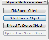
Physical Mesh Parameters rollout (Custom)
Use the Custom physical mesh type to extract a physical mesh from another object in the scene. This option gives you control
over the exact vertex placement of the physical mesh.
For best results with Custom meshes, observe these precautions:
- The object used as a Custom mesh must have no more than 256 vertices.
- To use a Custom mesh with a dynamic or kinematic rigid body, it must be convex; with a static body, it can be concave.
- The default location of the physical mesh derived from the Custom mesh is that of the source object, so in general you'll
want to superimpose the Custom mesh object and the object to serve as a rigid body before you extract the mesh. Otherwise
you can move the extracted mesh to the desired location at the Mesh Transform sub-object level of the Rigid Body modifier.
- Pick Source Object
-
Click this button and then select another object in the scene to use as the custom mesh. After selecting the mesh, the button
label text is the name of the custom mesh object.
Selecting a mesh copies the vertices of that mesh as the custom physical mesh. If you change your custom mesh in the scene,
click Update From Source Object (see following) to copy the changes into the physical mesh.
- Select Source Object
-
After you associate an object in the scene as the source for the Custom physical mesh, click this button to select that object.
If you then edit the source object and click Update From Source Object, the custom mesh picks up the edits.
- Extract To Source Object
-
When there is no associated Custom mesh in the scene (possibly because it was deleted), click this button to create a new
editable mesh obect from the physical mesh and associate it with the physical mesh. You can then tweak its vertices, use Update
From Source Object (see following), and then delete the editable mesh again if you like. Unavailable if the source object
exists.
- Update From Source Object
-
If you edit the vertices or transform the source object, click this button to copy the changes to the physical mesh. Unavailable
if the source object does not exist (for example, if you deleted it).