PolyDraw provides tools for quickly sketching out and editing a mesh on the main grid, projected onto the surface of another object, or on the selected object itself, depending on the Draw On setting. PolyDraw also provides Conform tools for molding one object to the shape of another.
The tools have different effects depending on which combination of the Ctrl, Shift, and Alt keys you press, as described in the following definitions. PolyDraw does not require that a particular sub-object level be active, but we recommend that you use them at the Vertex level for improved visual feedback with certain tool effects. To exit a PolyDraw tool, click its button again or right-click in the active viewport.
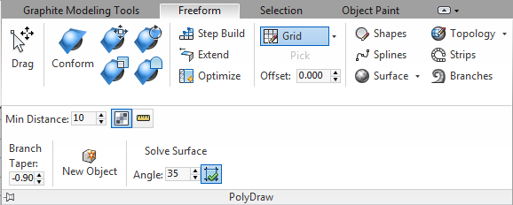
PolyDraw panel on minimized ribbon
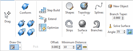
PolyDraw panel on maximized ribbon, with expansion
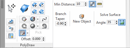
PolyDraw panel floating, with expansion
 Drag
Drag
With the Drag tool you can move individual sub-objects around on the surface or grid. The options are:
You can also use Drag to move sub-objects in screen space; that is, perpendicular to the current view direction. You do not need to change the active coordinate system to use this method.

 Conform Brush
To see an example of using the basic Conform brush to mold a plane onto a character's face, play the following video:
When any Conform Brush tool is active, the Conform Options panel opens. Use its settings to control the tool behavior and brush properties.
In addition to the basic Conform Brush tool, four transform-based variants are available:
 Move Conform BrushMoves vertices within the spherical brush volume along the target surface while conforming vertices to the target surface.
 Rotate Conform BrushRotates vertices within the spherical brush volume about the brush center while conforming vertices to the target surface.
 Scale Conform BrushScales vertices within the spherical brush volume about the brush center while conforming vertices to the target surface.
 Relax Conform BrushApplies a relax effect to vertices within the spherical brush volume while conforming vertices to the target surface.
 Step Build
With Step Build you can build and edit a surface vertex by vertex and polygon by polygon. Works at the object level and all sub-object levels. Right-click to exit the tool.
Following are the different functions of the tool, depending on which keyboard keys are pressed:
 Extend
With the Extend tool you can work on the open edges of the object; those on the border of the surface that have only one polygon attached. Following are the different functions of the Extend tool:
You can also use Extend to edit the object in screen space, thus moving sub-objects perpendicular to the view direction. You do not need to change the active coordinate system to use this method.
 Optimize
Optimize meshes quickly by sketching away details. The tool options are:
From the drop-down list, choose the entity type to draw on:
 GridPolyDraw creates geometry on the grid of the active viewport.
This drawing mode is particularly suited to orthographic viewports, but also works well in perspective viewports.
 SurfacePolyDraw creates geometry on an object that you specify.
Click the Pick button and then select a different object to draw on. The button then contains the name of that object. Use any of the PolyDraw tools (Strips, etc.) to draw on the object. To change the surface, click the button again and choose a different object to draw on.
 SelectionPolyDraw creates geometry on the selected object.
 Shapes
Draw polygon shapes on the grid or a surface.
Drag to set the polygon outline on the grid or an object surface. After drawing a polygon, optionally use Solve Surface to create a workable mesh from the shape.
While Draw Polygon is active, the following keyboard alternatives are available:
 Topology
Draw lines that form a grid of quads. As you draw eligible quads, Topology fills them in with polygons, creating a mesh from the grid. Right-click to exit the tool.
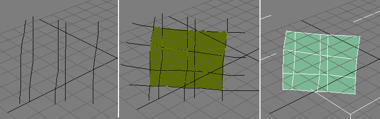
Left: Starting to draw the grid
Center: Completing the grid, with polygons created
Right: The result of using Topology (after right-clicking to exit)
If Auto Weld (see following) is on, the software automatically attaches the created mesh to the selected object and welds border vertices that are close together. This way you can continue adding to the surface of the selected object.
When Auto Weld is off, drawing with Topology always creates a new object.
The Minimum Distance value determines the resolution of the lines. If the value is too small some faces might be missed in the polygon creation. The default value, 10.0, with the unit type set to pixels should work well in most cases.
While Draw Topology Pattern is active, the following keyboard alternatives are available:
 Splines
Draw splines on a surface or grid. You can then make these splines renderable or use them in a lofting operation to create quick details.
Set the Draw On option, click Splines, and then drag to draw the splines on the desired base. All splines are combined into a single, separate object.
While Splines is active, the following keyboard alternatives are available:
 Strips
Paint strips of polygons that curve to follow the mouse direction.
The Strips tool lets you quickly lay out the topology foundation for a mesh object.
While Strips is active, the following keyboard alternatives are available:
Alternatively, press Alt before drawing and then drag between two open edges to connect them with a new polygon.
 Surface
Drag to paint a surface onto an object or the grid.
The following options are available:
 Branches
Paint multi-segmented extrusions from polygons with optional tapering to form "branches.”
The extrusions are aligned to the screen. The Branch Taper value (see following) determines the difference in size between the first and the last polygon in the branch, while Minimum Distance lets you set the distance between segments in the extrusion.
Activate the tool and then drag from polygons on the selected object to draw branches.
While Branches is active, the following keyboard alternatives are available:
The amount by which branches taper as you draw them. A negative value makes the branch dwindle in size; a positive value makes it get thicker, and 0 keeps it the same size as the starting polygon.
A value of -1.0 makes the end of the branch as small as possible, while values lower than -1.0 cause the branch to shrink to the minimum partway through and then enlarge the rest of the way.
 New Object
 Solve Surface
 Solve to Quads
The shortest distance you need to drag the mouse before the next step in the tool is taken.
For example, when using the Shapes tool, this value determines the minimum distance, in pixels or world units, between the vertices the software creates as you draw.
To determine how to measure Minimum Distance, choose one of the following:
 in PixelsUses pixels to specify the minimum distance you need to drag the mouse before the next step in the tool is taken.
 in UnitsUses world units to specify the minimum distance you need to drag the mouse before the next step in the tool is taken.
This panel, which floats by default, opens when any Conform Brush tool is active, and provides settings for modifying the tool's effects.


