Spline mapping is useful for mapping curved objects with a cylindrical cross-section, such as a snake or tentacle, as well as curved flat
surfaces such as a winding road. This feature lets you use any spline to specify mapping on a mesh surface, as well as manipulate
the mapping gizmo via cross-sections for greater accuracy. The result more closely approximates the actual shape of such objects
than other mapping methods, making it easier to create convincing texture maps.
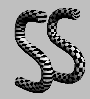
The following illustration shows two objects that were created by extruding a circular polygon along an S-shaped spline. Such
objects have no native mapping coordinates. The object on the left uses simple planar mapping, with the plane parallel to
its largest dimension. The object on the right uses spline mapping, with the spline (also used to extrude the polygon) inside
the object.
Working with Cross-sections
You can adjust spline mapping in two ways:
- By manipulating the assigned spline. To use this method, you must exit the modifier, select the spline, and then transform it or its sub-objects (typically the
vertices). To see the results of such manipulation, you must re-select the mapped object, go to the Face sub-object level,
and then click the Spline button.
- By manipulating the cross-sections in the Unwrap modifier.This is the recommended method because it provides better feedback. Thus, it is important to make sure the spline fits the
mapped object well before applying the spline mapping. If you have problems manipulating the cross-sections, sometimes the
fastest way to recover is to delete the Unwrap UVW modifier and start fresh with a new one.
When manipulating cross-sections, keep the following points in mind:
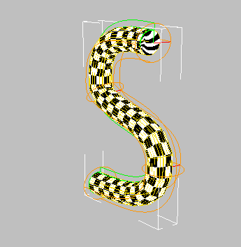
- When Spline mode is active (that is, the Spline Map Parameters dialog is open), you can select and transform only cross-sections.
To select cross-sections, use standard methods, such as clicking, Ctrl+clicking, region-selecting, and, to select all cross-sections, Ctrl+A. Selected cross-sections are yellow, and unselected ones are orange.
- All cross-section transforms take place in the Local coordinate system.
- Moving a cross-section on the Z axis always moves it along the length of the spline used for mapping. However, doing so does
not change the mapping between the moved cross-section and the next one. For example, moving a cross-section closer to its
neighbor does not compress the intervening texture coordinates. The main reason for having cross-sections close together is
for finer control over mapping within complex areas of the model.
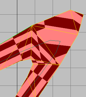
- With the Planar mapping method, it’s important to use well-formed mesh objects; that is, objects without narrow bends, with
evenly spaced tessellating edges that cross the “track” perpendicular to its sides. In particular, avoid objects with the
following two characteristics:
- Narrow bends. In particular, this type of shape can cause tessellating edges that connect to the same side instead of crossing
the “track,”as shown in the following illustration.
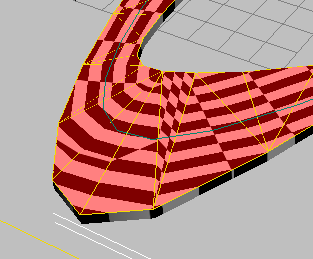
- “Fan” edges, where several edges share a single endpoint. This can cause the type of mapping anomalies shown in the following
illustration.
Procedure
To use Spline mapping:
- Create a mesh object to map, and a spline with which to specify the mapping. Position the spline inside the mesh object. For best results, always center the spline inside the mesh.
- Apply Unwrap UVW to the mesh object.
- Go to the Polygon sub-object level, and then select the polygons to map. To map the entire object (that is, all polygons),
leave all faces unselected.
- On the Wrap rollout, click
 (Spline Mapping).
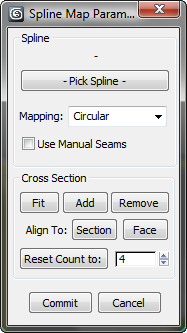
The Spline Map Parameters dialog opens.
- Click the Pick Spline button, and then select the spline to use for mapping. Either click the spline in the viewport or press
H and select it by name.
At this point, or if you already applied a spline, the mapping gizmo appears around the spline, showing the outlines and cross-sections.
- If necessary, modify the mapping by transforming the cross-sections in the viewports and adjusting the Spline Map Parameters
dialog settings. Keep in mind that changes affect only the mapping on selected faces, unless no faces are selected, in which case changes affect the mapping on all faces.
- If you use the Planar mapping method, make sure the cross-sections are parallel to the flat surface. One way to do so is to
select all the cross-sections (press Ctrl+A), then click the Align To: Face button, and then click a face on the surface.
Interface
Spline group
These settings are for overall mapping.
- Pick Spline
-
Lets you specify a spline to use for mapping. Click this button and then select the spline. After you specify the spline,
its name appears in the space above the button.
If the spline contains several elements, the element used for mapping is the one you click.
- Mapping
-
Lets you specify how the modifier projects the map onto the mesh.
- Use for objects with a circular cross-section, like a tube.
With circular projection, the cross-sections are circular by default. You can change the mapping by transforming these cross-sections.
For example, you can create a spiral mapping effect by rotating the cross-sections around their local Z axes by successively
greater amounts.
- Use for flat objects, like a road.
With planar projection, the cross-sections are lines. For best results, make sure the cross-sections are parallel to the mesh
surface, and perpendicular to the spline used for mapping. In most cases, this happens by default.
- Use Manual Seams
-
When on, uses the pelt seam as the texture border. When off, uses the green seam line built in to the spline-mapping gizmo.
This option is available only with Circular mapping, and works best with relatively simple objects with open ends.
Cross Section group
After you assign a spline in the Spline group (see preceding), 3ds Max applies the spline mapping to the object, creating a cross-section for each vertex in the spline. The settings in this group
let you manipulate the cross-sections. To select a cross-section, click it. To select all cross-sections, press Ctrl+A.
In Spline mode you can transform selected cross-sections in the local coordinate system, moving, rotating, and scaling them
as you like to adjust the texture coordinates.
NoteIf you have two cross-sections close together with very different orientations or scaling values, the mapping might show visual
anomalies (such as pinched UVs) as the Unwrap modifier interpolates quickly from one section to the next.
- Fit
-
Resizes selected cross-sections to match the adjacent geometry.
NoteWith asymmetrical geometry, Fit might give unexpected results because it adjusts the cross-section to the closest parts of
the neighboring geometry along the cross section's local X and Y axes. In such cases, you might need to transform the cross-section
manually to get the best fit.
- Add
-
Lets you add cross-sections for finer control over the interpolation of the mapping between cross-sections. Click this button
and then click the spline where you want to add a cross-section. The mouse cursor changes to a crosshairs when over the spline.
Continue adding cross-sections as necessary, and then click the button again to exit Add mode.
- Remove
-
Deletes any selected cross-sections. The end cross-sections cannot be deleted.
- Align To:
-
- Reset Count to
-
Lets you specify the number of evenly spaced cross-sections. Set the numeric value and then click the Reset Count To button.
This tool is useful when the mapping spline has many vertices, and you want to reduce the number of cross-sections to a manageable
number.
Commit/Cancel
- Commit
-
Applies changes and closes the dialog, exiting spline-mapping mode.
- Cancel
-
Discards changes and closes the dialog, exiting spline-mapping mode.
 Command entry:Unwrap UVW modifier
 Polygon sub-object level