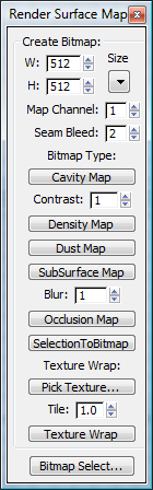
This dialog provides a set of tools for creating bitmaps based on an object’s UVW mapping. The bitmaps display certain surface properties of the object. There’s also a Bitmap Select function for selecting sub-objects based on mapping attributes.
Also, the object must have a map channel (typically 1) corresponding to the current Map Channel setting on the Render Surface Map dialog. If the object has no map channel, an error message informs you of this fact. To provide a map channel, apply an Unwrap UVW or UVW Map modifier and then convert the object to an editable poly.
Example: To use Render Surface Map:
This procedure describes how to create a surface map and then use it in a material.
Also, for best results, make sure mapping clusters do not overlap. For example, in the Unwrap UVW modifier, use the Flatten Mapping tool.
For example, to generate a texture that makes the object look dirty in concave areas, use Cavity Map.
After a brief pause, the generated texture opens in a separate window. The texture type (such as Cavity Map) appears in the window’s title bar.
 (Save Image). Specify a name, type (graphics format), and location for the file, and then click Save.
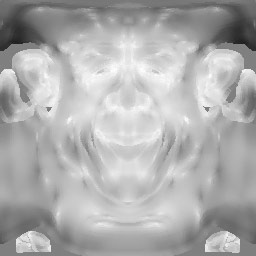
Generate a grayscale image that displays how convex or concave the surface of an editable poly object is at a given point. The more concave the surface is the darker the pixels will be and the more convex the surface is the more white is added to the pixels.
This image can be used as a cavity or "dirt" map, or as a base for further texture painting.
A Cavity map created from a character head
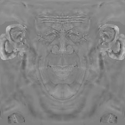
Generates a grayscale image that the extent to which each point in the surface faces the world Z direction. White represents vertices pointing fully in the Z direction and black represents vertices pointing 90 degrees from the Z axis (that is, parallel to the world XY plane) or below.
A Dust map created from a character head
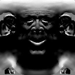
Generates a grayscale image that displays an estimation of the relative volume of a poly object at a given point. White represents the thinnest parts and black represents the thickest parts. You can then use this map to simulate greater translucency in thin areas.
The resulting map does not necessarily represent accurately how light would pass through the surface but can be useful for simulating this.

SubSurface maps created from a poly mesh, showing different Blur values
The upper two images use flat shading so that only the texture is visible.
Generates a black-and-white bitmap based on the current sub-object selection and displays it in a window from which you can save it.
White areas in the output image indicate selected sub-objects at that location. At the vertex level each vertex gets a white dot. At the edge level each edge gets a dot in the middle of the edge. At the polygon level each polygon is filled with white color.
You can use a bitmap generated with SelectionToBitmap for selecting sub-objects with the Bitmap Select tool (see following).

SelectionToBitmap used at the Vertex level
This tool creates a texture map from an input texture and wraps it around the selected object in a way that creates no texture seams and with a uniform texture scale across the surface. It projects the input texture from all directions and blends the result based on surface normal. A good use for this tool is to provide a base texture for a model. For example, you can create a basic skin texture and wrap that around the whole character model in a seamless way. Another use is for complex shapes such as a tree and all its branches.
To use Texture Wrap, first click Pick Texture to specify a texture file, then select the object to wrap and click Texture Wrap.
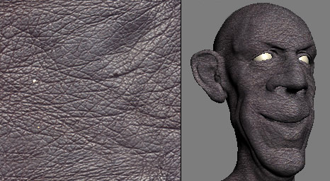
The input texture (left) and the resulting wrapped texture applied to a model (right)
With Bitmap Select you can select sub-objects in the model based on a bitmap image. Bitmap Select applies the chosen bitmap for selection purposes based on the model’s UVW mapping (it need not be part of a material applied to the object), and uses it to select parts of the mesh that correspond to a defined color. For example, you can select all polygons that have the color white in the chosen bitmap.


 Size
Size