Chapter 13, Pixel Expressions
| PXL Tool | |||
Chapter 13, Pixel Expressions |
|||
Use the CTL tool to write a color transformation language (CTL) expression to control the resulting appearance of a pixel.
Note: The CTL tool can only perform point operations--see-- Image Processing Algorithm Categories.
The CTL tool uses the same UI as the PXL tool--see PXL Tool UI.
The CTL tool supports every feature of CTL. For a more complete list, refer to the CTL manual: http://ampasctl.sourceforge.net/CtlManual.pdf. The main function of the script will be called for each pixel of the output image.
Before applying a script, several conventions must be respected:
The entry point of the script is the "main" function. This function must be present in every script.
The main function return value is ignored.
The main function must have four parameters for each input image. They correspond to the RGBA channels of the pixel of the input image. They must be of type float, and be qualified as "input varying". The name of these parameters must be the component letter in lower case (i.e. "r", "g", "b", and "a"), concatenated with the name of the input image. Because the primary input of the CTL tool is called "In", the corresponding arguments to the main() function for that input image will be:
input varying float rIn
input varying float gIn
input varying float bIn
input varying float aIn
Additional images (if any) follow the same convention: for an additional input image Bg, the corresponding arguments to main would be:
input varying float rBg
input varying float gBg
input varying float bBg
input varying float aBg
4 parameters of the main() function must be present to define the output pixel color. They correspond to the RGBA channels of the output pixel. They must be of type float, and must be qualified as "output varying". The name of these parameters must be the component letter in lower case concatenated with the literal string "Out":
output varying float rOut
output varying float gOut
output varying float bOut
output varying float aOut
1 parameter of the main function must be present for each input parameter. They must be the same name and type as the parameter of the UI. Ex:
input uniform float P1
The following is a sample script and procedure that blends two images.
Connect a CTL tool node into an output node in the Schematic view.
Connect image 1 to the In input of the CTL tool.
Create a second input for the CTL tool by right-clicking on the node and selecting Add input from the menu.
Name the new input Img1 when prompted.
Connect a second image to Img1 input.
Select the CTL tool node and click the Edit button to open the Toxik internal editor.
Type the following script into the editor or copy then paste it in using Ctrl + C and Ctrl + V:
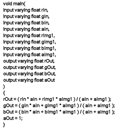
 "Show full-size image")
The two images are blended.
Note: Toxik fully supports the CTL import statement and the CTL_MODULE_PATH environment directory. As such, it can be convenient to structure CTL code in Toxik such that the main() function above is used simply as the entry point that calls other CTL functions defined in separate files that are imported with the import statement.