Chapter 8, Multilayer Compositing and 3D Effects
| Camera Mapping | Transforming Objects | ||
Chapter 8, Multilayer Compositing and 3D Effects |
|||
The 3D Displacement tool lets you add depth to meshes created in or imported into Toxik. The pixel values in an image are used to displace vertices. This allows the illusion of perspective to be maintained as the camera is moved in 3D space. You can also create a displacement that conververges on an object, such as a light. Once created, you can blur the displacment, as well as set the tiling.
 "Show full-size image")
|
|
|
Note: The 3D Displacement tool can only perform displacement on images with sufficient geometry. If the image you are using does not contain sufficient geometry, you can increase it by adjusting the width and height of segments in the Surfaces tab of Reaction.
Select Composition > New or press Ctrl + N to start a new composition.
From the Tools tab, select Camera from the Reaction folder and drag it to the Schematic view.
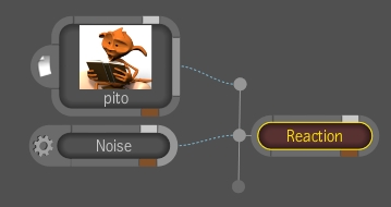
You will need two sources, one for the image to be displaced and another for the image that will do the displacing. Right-click the Reaction node and select Add Source. Repeat to add another source.
Select the Reaction node. In the Tool UI, select the Render tab and click Z-Buffer--see Enabling Z-Buffer Effects in Your Scene.
Add the two images you want to use to the Schematic view, connecting one to each source. In the following example, the Noise image generator is used to displace the character.
 "Show full-size image")
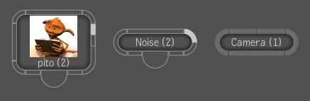
Display the Group Schematic by double-clicking the Reaction node or right-clicking the Reaction node and selecting Edit Group.
 "Show full-size image")
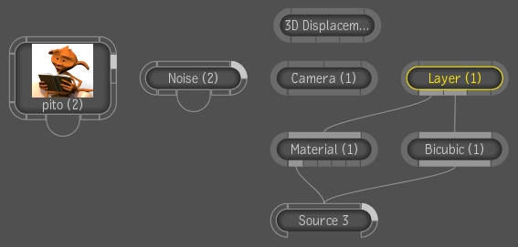
From the Tools tab, select 3D Displacement from the Reaction folder and drag it to the Group Schematic.
In the Layer Editor, click Create to add a new layer.
 "Show full-size image")
Delete the Source node and arrange the nodes as follows:
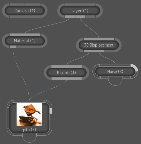
 "Show full-size image")
Select the 3D Displacement node. In the Tool UI, you can adjust the following parameters:
| Parameter | Description |
| Amount | Amount of displacement in the image. Positive values make the displacement protrude and negative values invert the displacement. Note: The displacement occurs in Reaction units (Amount times the displacement image values minus the Offset). |
| Offset | The value that is subtracted from the displacement image values before it is interpreted as a displacement. It is used to determine the value of the displacement image that yields no displacement. |
| Type |
|
| Channel | Set the channel for displacement: Luma, Red, Green, Blue, Alpha. |
| Convergence | Used with the Toward Target type. The displacement converges or is parallel to the target. |
| X Radius, Y Radius | Set the amount of blur to apply in the X or Y direction. |
| Link | Couple the X and Y Radius so that when you change the X Radius or Y Radius, the other changes in the same proportion. |
| Tiling X, Tiling Y | Set the repeat mode: Transparent, Edge, Repeat, and Mirror. |
To make the displacement point towards a target, set the Type to Toward Target. Set Convergence parameter; the displacement can converge on the target or be parallel to it.
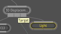
From the Tools tab, select the Reaction folder and drag one of the following to the Group Schematic: Axis, Camera, Layer, Light, or Locator.
Connect the target to the Target tab of the 3D Displacement node. In the following example, a light was added as the target.
 "Show full-size image")
Select the Light node. In the Lights tab, adjust the light to your liking--see Working with Lights.
Select the 3D Displacement node and adjust the Amount until you have the desired result.
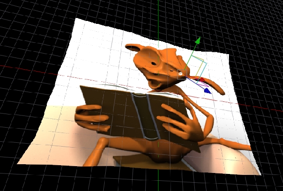
 "Show full-size image")
The image is starting to displace towards the light object.