You can add clips to the Batch schematic in the following ways:
When you load or import clips from remote clip libraries, Batch does not duplicate storage on the local framestore. The import process occurs one frame at a time as you jog the timebar. In this way, the framestore is not cluttered with duplicate information.
To add clips to the schematic:
| Select: | To: |
|---|---|
| Desk node | Add clips from the Desktop reels. You can select up
to six clips. Click Exit Clip Select to return to Batch. See Desk Node. |
| Library node | Load clips from a local or remote clip library. Select the clips and click Load to return to Batch. See Library Node. |
| Import node | Import images and clips using the Import Image module. See Import Node. |
You return to Batch and your selected clips are displayed as proxies in the schematic.
To replace a clip in the schematic:
In the Batch schematic, the original clip is substituted for the new selection.
Importing Multiple Resolutions
You can import clips of resolutions other than the default resolution defined for the project. The resolution and aspect ratio display directly on the clip in the schematic. Proxies are also displayed in their correct aspect ratio.
Nodes with multiple inputs, such as the Keyer and Colour Warper, must use clips of the same resolution. For example, the Front and Back inputs must be of identical resolution. If you want to add a clip with a different resolution as an input, you must either parent a Resize node between the clip and the input of the node, or resize the clip itself. For Action nodes, each Action layer must also use a front and matte of the same resolution. However, separate layers can have different resolutions.
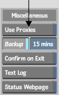
Use proxies to work with low-resolution versions of your high-resolution material. Using an image's proxy to perform colour corrections, blurs, or other edits significantly increases the interaction speed. Proxies of your clips are generated according to your project settings and conditions.


All clips replace their respective proxies as defined at project creation. The image window is outlined in amber.
OpenEXR-formatted clips loaded from the Flame or imported from the library into Batch.
A selection of Batch nodes supports direct OpenEXR input. See Batch: Node Reference. If a clip is stored at 16 bits and connected to a node that does not support floating point data, its red warning tab is activated. To connect an OpenEXR-formatted clip to a node that does not support OpenEXR input, apply a conversion and export it to a linear format.
In Batch, you can apply a conversion in EXR Display by:
You can use a LUT Editor node to apply a conversion to an OpenEXR-formatted clip. If a clip is stored at 16 bits, and you want to connect it to a node that does not support floating point data, you must first attach it to a LUT Editor node to apply a linear conversion to the clip.
You can apply a conversion directly to a clip. When stored as linear data, you can connect the clip to any node in the schematic. You have the option of changing the clip's bit depth, including returning the clip to a bit depth of 16 bits, allowing you to work with the clip's high-dynamic range properties.
See Converting OpenEXR Images and LUT Editor Node.
To apply a conversion directly to a clip: