Adding Nodes


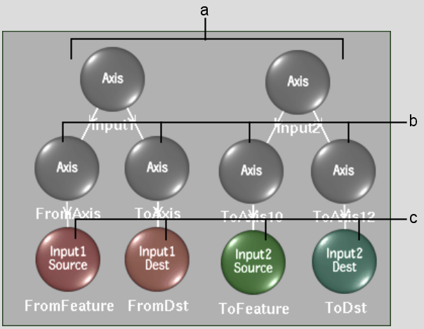
When you add a spline, a spline node tree is added for Input1 or Input2. The spline node tree includes both Spline and Axis nodes.

You can add additional Axis nodes to the schematic.

To add a spline node tree:

  1. Select Input1 or Input2 from the Input box, depending on where you want to add splines.
    NoteSplines can be changed from Input1 to Input2, or from Input2 to Input1. See Toggling Spline Nodes from One Input to Another.
  2. Select Spline from the Node box.
  3. Click Add.
  4. Draw a spline. See Drawing Splines.

    A spline node tree is added for either Input1 or Input2 in the schematic. It includes source and destination spline nodes, each parented to their own Axis node, which are in turn parented to a common axis.

    Show small imageShow large image

    (a) Spline node trees for one Input1, and one Input2 spline  (b) Axis nodes for individual spline wireframes  (c) Spline nodes for corresponding source and destination splines  

To add an Axis node:

  1. Select Axis from the Node box.

    Show small imageShow large image

  2. Click Add.
    TipTo add an Axis node between two linked nodes, hold Shift and drag the Axis node on top of the link. To remove an Axis node between two linked nodes, hold Alt+Ctrl and drag the node away from the link.