Component selection and transformation is one fundamental method for editing the shape of a polygon mesh. As you model, you’ll find yourself frequently examining and then refining the position of the polygon components (vertices, edges, and faces) while working in the various scene views so they match the reference images on the image planes.
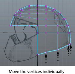
To manually reposition the vertices on the rear of the helmet
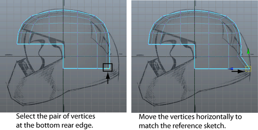
By moving the vertex as well as the vertex adjacent to it along the axis of symmetry, you ensure that the symmetrical shape of the helmet is maintained. If you move one vertex independently of the other it may result in an unwanted bump or valley in the mesh. These types of anomalies will become more apparent when you copy the completed half of the mesh across the axis of symmetry.
When you have finished, the back region of the helmet should closely match the reference image on your image plane.
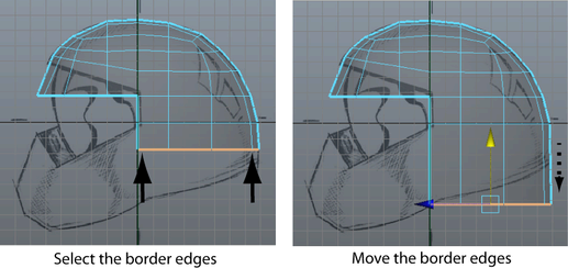
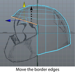
Next, you’ll reposition the border edges that lie along the bottom edge of the mesh. You can select these edge types using the Select Border Edge Tool.
To reposition the lower border edges on the helmet
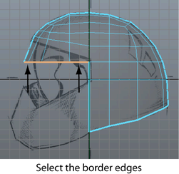
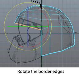
To edit the border edges on the upper edge of the face shield
The border edges in between are selected.
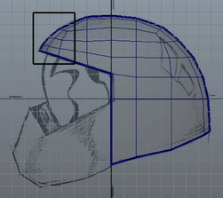
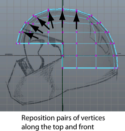
At this point in the lesson, the outline of your helmet should roughly match the helmet in the side view reference image. If it doesn’t, review the earlier steps in this lesson and make any adjustments to your polygonal mesh as required.
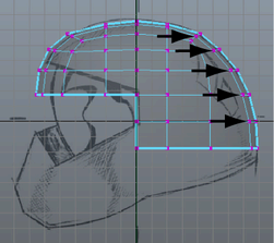
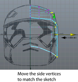
If you view your helmet in the front orthographic view, you’ll notice that the helmet shows a wider profile from this view than the reference sketch. In the next steps you’ll correct this using the front and top orthographic views of the helmet for reference.
To reposition vertices on the side of the helmet to match the sketch

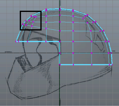
When you view your helmet from the top orthographic view the region between the side and rear of the helmet appears a bit flat in relation to the other areas.
To correct this you can move the other vertices in this region outwards in a similar fashion so the curvature in this area appears fuller and more rounded. However, viewing only from the orthographic views can be limiting, and you should also use the perspective view to examine the mesh.
To examine the mesh using the perspective view
As you examine the vertices along any particular edge loop, the vertices on the mesh should appear to cascade in a smooth gradual fashion to create the curvature of the mesh with no undesirable spikes or dips.
Ensuring that the mesh appears relatively smooth at various stages throughout the modeling process will reduce the possibility for issues when you create a high resolution version of the mesh later on.
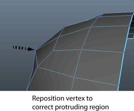
If you find areas where one vertex (or more) appears to protrude outwards (or recedes) on the mesh in relation to neighboring vertices, you can correct these protruding regions by repositioning the affected vertices in the perspective view.
To prepare for the next part of the tutorial open the Helmet1.mb scene file (File > Open Scene) or continue working with the current scene.


