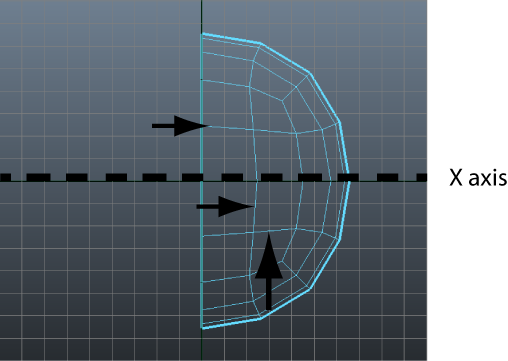
In the top view, the rows of edges immediately above and below the X-axis, and the row to the right of the Z-axis are not straight. You’ll want to align the edges in these rows (referred to as edge loops) by snapping them to the grid using the Move Tool. An edge loop is a path of polygon edges that are connected in sequence by their shared vertices. Edge loop selections are very useful when you model using polygons.

To align edges on the helmet mesh

Snap to Grids lets you move selected components to the closest grid line or grid intersection point. When many components are selected, you can align them to each other via the grid simultaneously.
The edge loop immediately snaps to a lower grid line. It is not positioned at the location you want, but all of the edges in the loop you selected are now aligned to each other.
When you have finished, the edge loops nearest the X and Z axes are aligned. (see image below)

 Except where otherwise noted, this work is licensed under a Creative Commons Attribution-NonCommercial-ShareAlike 3.0 Unported License