MatchMover manages a set of user-defined coordinate systems with respect to the cameras and 3D points in the Workspace. If no coordinate system is specified, MatchMover chooses an arbitrary one. You can define a coordinate system in order to facilitate the manipulation of your exported project in a 3D package. If no point relations have been set up, MatchMover aligns the coordinate system on the computed position of the camera for the first frame; the default is the camera looking towards Z and Y as Up axis, but this changes according to your project's 3D parameters if you selected a different up axis.
To ensure this lesson works as described, do the following:
To set MatchMover to Full mode, select Full from the MatchMover toolbar.
To switch MatchMover to 3D mode, click the 3D space icon  that is located in the top left of the Workspace view. If a 2D space icon
  appears instead, then MatchMover is already in 3D mode.
Setting up the coordinate system
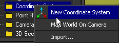
To set up the coordinate system
For your new coordinate system values, you will use Track 05 as the origin. This point is the center of the grid and floor of the scene.
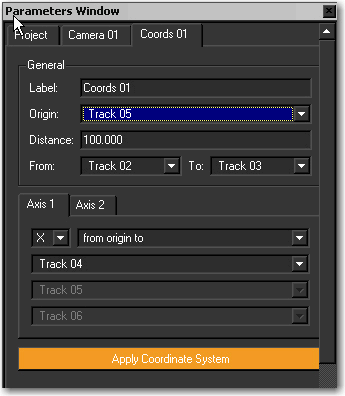
This value defines the distance between two points in the scene.
These two points provide tracking locations in the corners of the room, making them well suited for defining the boundaries of the coordinate system.
These settings create a Y-based coordinate system using three points that are located on the ground of the scene.
These settings create a Z-axis as the second axis which is based on the crosses on the wall of the scene background.
Now that you have defined a 3D coordinate system in MatchMover, you can import an object into the Workspace and check its behavior in the scene.
 from the primitive list located on the Toolbar.
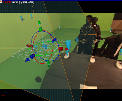
The pyramid primitive appears in the Workspace at the origin of the coordinate system. A Pyramid tab appears in the Parameters window displaying the pyramids position and scale.
The pyramid is too large for the scene. You can make the pyramid smaller by using MatchMover’s scaling tools.
The scaling tools appear as a series of light blue, dark blue, green, and red cubes surrounding the pyramid.
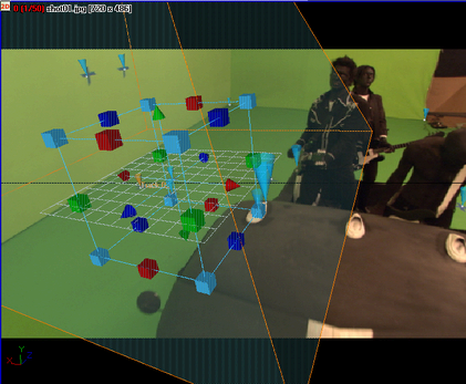
Notice that as you drag the cursor, the X, Y, and Z values are scaled uniformly.
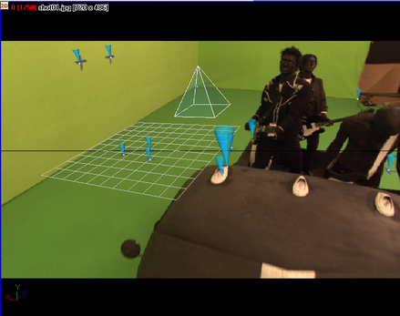
Notice that the tip of the pyramid is out of the camera view. You can use the move tool to change the pyramid’s position so that it remains in the camera view throughout the sequence.
Notice that the pyramid remains in the camera view throughout the sequence.
You can now export the sequence and verify its tracking quality in your favorite 3D animation or compositing program.
For example, to open your tracked image sequence in Maya, select Maya (*.ma).
The image sequence is exported to the specified file format.


