Subdivision surfaces are created by repeated refinement of polyhedral control meshes according to certain subdivision rules. The control mesh is basically a polygon mesh with certain restrictions (triangles and quads only) and certain extensions (for creases, for example), which is approximated more and more finely to generate a smooth limit surface. The limit surface obtained by this process is tangent-plane smooth at extraordinary vertices and curvature smooth at regular vertices. The main advantage of subdivision surfaces over NUBRS is their ability to define arbitrary topology geometry, that is, they do not require a rectangular parameter domain.
Subdivision surfaces are available in mental ray as an optional product, called mental matter. Subdivision surfaces support can be added to mental ray either by linking the libmisubdiv.so in the same way a shader library is linked, or by using an integrated version of mental ray that combines mental ray and mental matter. The library implements approximation and management of subdivision surfaces, and has a powerful C++ API allowing multiresolution modeling operations. The .mi format allows definition of subdivision surfaces. For complex modeling operations geometry shaders using the above mentioned C++ API can be written. This API comes with a separate documentation, see [CAPI2].
The subdivision surface implementation supports the Loop scheme, which operates on a control mesh consisting of triangles, and the Catmull-Clark scheme, which operates on a control mesh consisting of quads (polygons with four vertices). Face refinement is adaptive, supporting the LDA approximation criteria described in section approx. Vertices may have features assigned which modify the subdivision rules. Detail vectors may be specified for vertices on any level in the face hierarchy for multiresolution representation. Trim edges can be specified on any level to cut holes into the surface. Edges can be tagged as a crease with fractional sharpness to model for example wrinkle features. All these features are described in the following sections.
Other features such as multiresolution modeling, approximation precision per face, face visibility, animation capabilities and NURBS export and import are not accessible from the .mi format. See [CAPI2] for details on these advanced modeling capabilities.
Subdivision surface geometry, like polygonal geometry, is defined by a series of sections. An object containing only subdivision surface geometry follows this broad outline:
    object "object_name"
        ... # flags, boxes, data, etc.
        group
            vector list
            vertex list
            subdivision surface
            ... # more subdivision surfaces
            [ approximation list ]
        end group
    end object
The vector list in the group is a list of (x, y, z) vectors used for face vertex positions, detail vectors, texture and motion vectors.
The vertex list that follows the vector list builds control vertices from the vectors. This works like the vertex list of polygonal geometry, except that no normals can be defined here. Here position vectors, texture coordinates and motion vectors can be referenced.
Features may be associated with vertices by specifying either corner, conic, cusp, dart or smooth behind the regular vertex definition:
    v vec_ref [ tex_list ] [ m motion_ref ] [ corner [ level level ] ]
    v vec_ref [ tex_list ] [ m motion_ref ] [ conic [ level level ] ]
    v vec_ref [ tex_list ] [ m motion_ref ] [ cusp [ level level ] ]
    v vec_ref [ tex_list ] [ m motion_ref ] [ dart [ level level ] ]
    v vec_ref [ tex_list ] [ m motion_ref ] [ smooth [ level level ] ]
Here vec_ref is the reference of a position or detail vector, tex_list is a list of texture coordinates with t keywords and corresponding coordinate indices, and motion_ref is an optional motion vector. Only one motion vector may be specified for each vertex with mental ray 2.1 and 3.0, and up to 15 with mental ray 3.1.
The optional vertex feature follows, and an optional level can be specified if the feature is active on a level above vertex definition level. Texture coordinates may only be specified for base face level vertices. The vertex features are described in more detail in a separate section below.
The subdivision surface geometry list consists of subdivision surface statements, much like Free-Form geometry consists of surface statements. For a description of vector lists and vertex lists, refer to page vector.
The approximation statements are very similar to the free-form case, except that approximate surface is replaced by approximate subdivision surface. See section approx for details.
A subdivision surface specifies a name and a list of optionally refined base faces, followed by optional derivative request:
        subdivision surface "surface_name"
            [ texture_interpolation ]
            [ base_mesh ]
            [ derivative_request ]
        end subdivision surface
Triangles and quads can be mixed in the same subdivision surface, but they may not share vertices.
The base mesh of a subdivision surface is very similar to polygons. It uses the same syntax, but only faces with three or four vertices are allowed, since the Loop subdivision scheme operates on triangle meshes and and the Catmull-Clark scheme on quad meshes. The face vertices must be specified in counter-clockwise order, the mesh must be 2-manifold.
    p ["material_name"] vertex_ref_list
        [ crease crease_mask sharpness_list ]
        [ trim trim_mask ]
        [ { hira_spec } ]
The p keyword begins definition of a base face. An optional material name may follow, otherwise the material of the previous base face is assigned to the current base face. It the current object is marked as tagged, a label integer must be given instead of the material name (this is not shown here). Face vertices must be specified in the vertex_ref_list.
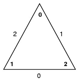
The optional crease statement allows specification of crease edges. With crease_mask up to four edges are selected for crease, the floating point sharpness values follow in the sharpness_list. crease_mask is a bitmap where crease edge indices are associated with corresponding bit positions in the mask. The diagram below shows the vertex and edge labeling of a base triangle:

The numbers inside the triangle indicate vertex numbers, the numbers at the three edges indicate the corresponding bit position in the crease bitmap. Bit 0 is assumed to be the least significant bit. Here is an example where edges 0 and 1 in a triangle should be crease edges, with corresponding sharpness values of 0.7 and 1.0:
crease 3 0.7 1
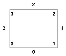
For quads the vertex and edge labeling is similar, as shown in this diagram:

For more information on crease edges, see section vertexfeature below. A base face may be trimmed with the trim statement. The trim_mask is a bitmap where trim edges are selected according to their index in the face, in a way very similar to the crease bitmap described above. For more information on trim edges, see section sdstrim below.
It is possible to explicitly subdivide faces and to specify detail. The surface begins with a base mesh, which is subdivided into finer and finer levels, until the final smooth limit surface is reached. These levels form a hierarchy with the base mesh at its root. Modeling allows control over the levels of the hierarchy, such that the subdivision is guided by predefining how the subdivision takes place by predefining vertices on higher levels. This is useful to introduce local detail. For example, a head can be modeled by defining the general shape as the base mesh, and the nose can be introduced by defining one or more higher levels that introduce the required local detail. It is sufficient to define higher levels only where detail is needed; it is not necessary to define all parts of a higher level. (This would very quickly require very large numbers of vertices, even where no detail is required.)
Definition of detail on higher levels of the hierarchy is done by subdividing a face of the next-lower hierarchy level. High-level vertices can not be placed just anywhere, but only by subdividing a triangle or quad that already exists on the next-lower level, in a fixed way by dividing its edges.
In the .mi scene language, a face is subdivided by specifying a pair of curly brackets around hira_spec. Inside the hira_spec block a configuration of four children on the next level is selected, called a kit. The kit specification hira_spec is defined as:
    [ child child_index { hira_spec } ]
    [ detail detail_mask detail_list ]
    [ trim child_index trim_mask ]
    [ crease child_index crease_mask sharpness_list ]
    [ material child_index material_name ]
    [ material child_index label
In all the statements above, the child within the kit is selected with a child_index. A child may be further subdivided explicitly by specifying a hira_spec block inside curly brackets. The maximum number of subdivision levels that can be specified is 15.
A detail vector specifies the offset to be added to the result of subdivision on a certain level for a certain vertex. The detail vector is specified in object coordinates, but is transformed using local reference frames. Adjacent subdivided faces automatically create a shared midpoint on the edge they share. A detail vector can be assigned using both faces, but a single assignment is sufficient since the vertex is shared.
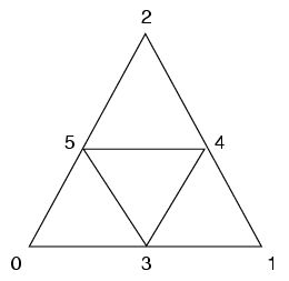
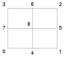
Detail vectors may be specified for the current kit vertices for the current subdivision level. A triangle kit has six vertices where detail vectors can be assigned, a quad kit has nine vertices. Detail vectors may be defined also on higher hierarchy levels above the current vertex definition level by explicitly subdividing the face and specifying details on the higher level kits.
The same detail vector may be assigned to different vertices, even on different levels, since there is no relationship between the vertices in the vertex_list and the vertices that are created automatically for the limit surface. Here the detail vectors are simply looked up in the vector list and their value is assigned to internal subdivision surface vertices.
Detail vertices for the current kit are selected with the bitmap detail_mask. Each vertex of the kit has a corresponding bit in the bitmap. The vertex labeling for a triangle kit is shown below:

For a quad kit the labeling is similar:

The detail vectors are specified with the detail_list, which is a list of vertex indices. For example, if a detail vector is given by vertex index 10 and it should be assigned to the central vertex of a quad kit, one would have to specify 256 for the detail_mask, followed by 10.
Crease edges on the kit subdivision level can be specified by selecting a child in the kit with child_index, followed by an edge mask selecting the edges within that child, and finally followed by floating point values specifying the sharpness of the selected edges.
Trim edges on the kit subdivision level can be specified by selecting a child in the kit with child_index, selecting one of the four children, followed by an edge mask similar to the trim mask for base faces.
Materials can be assigned to individual faces by using the material keyword, followed by a child index selecting the face within the kit, finally followed by the material name (or label index if the object is tagged). Materials are inherited in the hierarchy.
Vertices may be tagged with the following features to modify the subdivision rules:
Creases are discontinuities introduced into the surface in oder to define sharp geometric details such as wrinkles. Crease edges may be specified for edges which are not on the geometric boundary. Connecting crease edges must be defined on the same level.
A vertex with exactly two incident crease edges is internally marked as a crease vertex. Normal vectors for vertices on an infinite sharp crease line are not shared; instead, two normal vectors are created for the faces on each of the two sides on the crease line. A crease sharpness value of 0 assigned to an edge will result in smooth subdivision, a value of 1 results will generate an infinite sharp crease, and fractional values between 0 and 1 will generate smooth creases. Sharpness values of subsequent higher subdivision levels are computed using a quadratic B-Spline function applied to the sharpness values of the parent edges.
Trim edges may not be defined on the boundary or on crease edges. Connecting trim edges must be defined on the same level. Trim loops may not intersect or touch. Regions where faces are located inside a closed trim loop will generate a hole in the surface. It is not allowed to create trim regions within trim regions. It is legal to specify open trim loops, but here no holes are created in the surface.
When vertex features must be defined for vertices on trim loops above level 0, one has to reference a vertex defining that feature. If this vertex does not have significant detail, a zero length detail vector must be referenced to satisfy the .mi grammar in the vertex section.
At trim loops, boundary subdivision rules are applied.
mental ray can generate surface derivative vectors for subdivision surfaces if requested. They are computed and stored only if requested by derivative_request statements in the subdivision surface definition:
derivative numberint [ spaceint ]
For number 1 must be specified, higher derivatives are not supported. Since subdivision surfaces allow arbitrary topology, there is no intrinsic surface parameterization available, so a texture space which defines orientation of the derivative vectors must always be specified with the space number. The first t vectors in the vertex definition is space 0, the second is space 1, and so on.
Subdivision surface texture spaces can be created either using subdivision rules (interpolated between vertices, which is the default) or computed once per face, which linearly interpolates the texture coordinates within the face. The subdivision rule interpolated spaces will in general give a better mapping compared with the linear interpolation method. The interpolation method can be specified separately for each texture space with the optional texture_interpolation statement:
texture space [options]
options is a comma-separated list of either face for linear interpolation or subdivision for subdivision rule interpolation. The first t texture vertex statement in the vertex section corresponds to the first entry in this array; the options list has one member for each t statement in each vertex. (All vertices must have equal numbers of t statements.)
In the example below a cube base mesh is created, the four bottom level 0 edges are marked for infinite crease (1.0 for each edge), the top face is subdivided once and a detail vector is assigned to the central vertex on level 1.
    object "quadcube"
        group
            -1 -1 -1
             1 -1 -1
             1  1 -1
            -1  1 -1

            -1 -1  1
             1 -1  1
             1  1  1
            -1  1  1
             0  0  0.4

             v 0 v 1 v 2 v 3 v 4 v 5 v 6 v 7 v 8

             subdivision surface "surf1"

                 p 0 1 5 4
                 p 1 2 6 5
                 p 2 3 7 6
                 p 3 0 4 7
                 p 4 5 6 7 {
                     detail 256 8
                 }
                 p 0 3 2 1 crease 15 1 1 1 1

             end subdivision surface
             approximate subdivision surface angle 7 "surf1"
        end group
    end object
Copyright © 1986-2010 by mental images GmbH