User Guide > Rendering and Render Setup > Shading > Shading Nodes > Material nodes - Maya software > Surface materials >
Shared surface material
sections
The following sections of the Attribute Editor provide attributes that are shared between most materials.
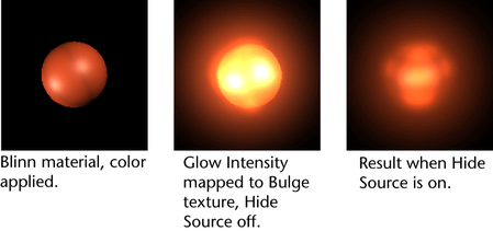
These attributes control the appearance of glows produced from light reflecting off surfaces, or from surface incandescence. Special Effects attributes are available for Anisotropic, Blinn, Lambert, Phong, and PhongE material types. See also Glow for more information.
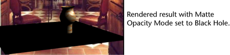
You can control the mask value for individual objects. Matt Opacity attributes are available for Anisotropic, Blinn, Lambert, Layered Shader, Phong, PhongE, Shading Map and Use Background material types.
This is the default Matte Opacity Mode. This mode produces both reflections and shadows.
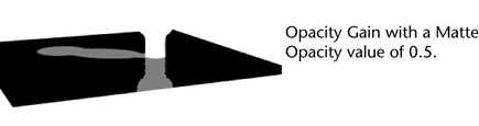
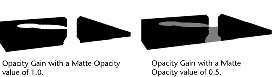
The matte channel is first calculated, and then multiplied by the specified Matte Opacity value. The Opacity Gain value is used as a multiplier on the matte value produced by this material.
The Matte Opacity Mode value is also keyable. The Opacity Gain range is from completely invisible to no effect (rendered as usual).
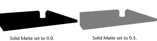
Solid Matte makes the value of the matte channel constant for the material. The value you specify in the Matte Opacity slider is used, instead of the default value.
Use Solid Matte to adjust the overall density or visibility of the Use Background material.
This value depends on which Matte Opacity Mode is selected (Opacity Gain or Solid Matte). For example, for Opacity Gain, the Matte Opacity value indicates the multiplier amount for the alpha channel. The default is 1, which means that any opaque material registers an unaffected alpha value.
Any values between 0 and 1 act as a multiplier to the alpha channel value to arrive at modified value. Use the slider or enter a value to adjust the density or visibility of the mask channels.
The Raytrace Options attributes control the appearance of a surface during raytracing only.
Raytrace Options attributes are available for Anisotropic, Blinn, Lambert, Phong, and PhongE material types.
The amount that light rays bend when passing through a transparent object. A Refractive Index value of 1 does not bend light rays at all, so you need to set the index value higher than 1. Refractive Index values for common materials are: glass (1.6), air (1), water (1.333), crystal (2), diamond (2.417). The valid range is 0.01 to infinity. The slider range is 0.01 to 3, but you can type in a higher value. The default setting is 1.6.
The maximum number of times the surface allows a light ray to be refracted. For example, if the Refraction Limit value is 10, the surface refracts light rays that have previously been refracted and, or reflected (off itself or off other surfaces) 9 times or less; the surface does not refract light rays that have previously been refracted and, or reflected 10 or more times. The valid range is 0 to infinity. The slider range is 0 to 10. The default value is 6. Increasing this value may significantly increase render times.
You must also consider the Render Settings window Raytracing refractions attribute too. Maya uses the lower value of the 2. For instance, if your limit is set to 9 on the material and 6 in the Render Settings window, a value of 6 is be used. See also, Reflection Limit
In the following example, a glass sits in front of a mirror.
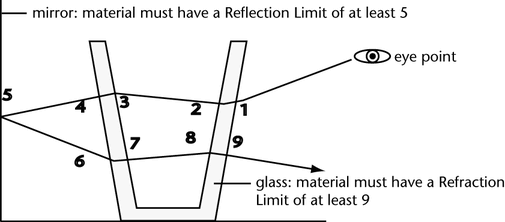
The number of refractions includes both the entry and exit of a light ray from a surface having thickness.
The physical property Total Internal Reflection (TIR) can make some transparent objects appear not to refract light. This is caused by light rays reflecting inside the thickness of the object. If this occurs, increasing Refraction Limit has no effect because the Reflection Limit is stopping light rays before they can exit the surface. However, because TIR is a real-world property, you may want to keep this effect.
The maximum number of times the surface allows a light ray to be reflected. For example, if the Reflection Limit value is 4, the surface reflects light rays previously reflected (off itself or off other surfaces) 3 times or less; the surface does not reflect light rays previously reflected 4 or more times. The valid range is 0 to infinity. The slider range is 0 to 10. The default value is 1.
Set the Reflection Limit value according to the material’s Reflectivity value. For example, if the Reflectivity value is between 0 and 0.5, set the Reflection Limit value between 1 and 2. If the Reflectivity value is between 0.5 and 1, set the Reflection Limit value between 2 and 5.
High values for Reflection Limit greatly increase rendering time. Test render the scene using various settings, and use the lowest values that give you acceptable results. Even highly reflective surfaces rarely need a Reflection Limit value as high as 10 or more.
You must also consider the Render Settings window Raytracing Reflection attribute too. Maya uses the lower value of the 2. For instance, if your limit is set to 5 on the material and 1 in the Render Settings window, a value of 1 is used. See also Reflection Limit.
This attribute is available for Blinn, Anisotropic, Phong, and PhongE materials.
Reduce this value to avoid highlight aliasing artifacts produced in reflections during raytracing because of very thin or small highlights. Maya adds Reflection Specularity to each material to control the contribution of the specular highlights in reflections. The valid range is 0 to 1. The default is 1 (full contribution).
Describes how light-absorbing a material is. A material with an Absorbance of 0.0 transmits completely. The higher the value, the less light passes through.
Transparent materials generally absorb an amount of the light which passes through them. The thicker the material, less light gets through—the thinner the material, more light gets through.
The simulated thickness (in world space) of transparent objects created from single surfaces (for example, a NURBS plane, or polygon face).
Using Surface Thickness does not produce the same results as building a surface with actual thickness—the effect works well when the edges of the surface are not visible (for example, closed surfaces, or bounded shapes, like a car windshield).
Shadows of transparent objects are brighter in the center, simulating a light’s focus. A setting of 0 results in constant intensity shadows. The focusing increases as the parameter increases from 0 to 1. The default value is 0.5. The amount of attenuation for a given light ray depends on the angle between the light ray and the surface normal of the transparent object: the greater the angle, the greater the attenuation. To turn off the shadow attenuation completely, set shadow attenuation to 0.
This is the ability to bounce indirect photons. Use this to map an incoming illumination map, such as one generated using Lighting/shading > Batch Bake (mental ray). For information about baking in general, see Baking illumination and color.
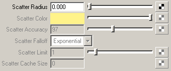
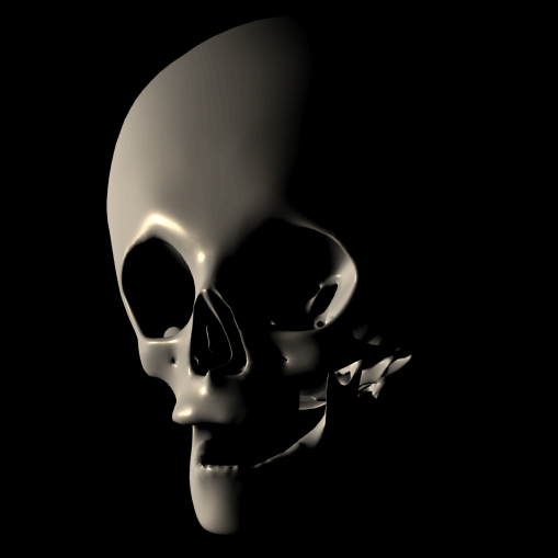
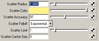
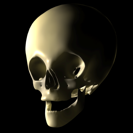
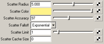
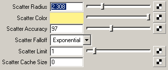
Determines how far light scatters under a surface. If the incoming light and the scatter radius are at an equal distance, mental ray assumes that all the light is absorbed by the material. The Scatter Radius attribute is in world space units, and has a default value of 0.
A value of 0 means that scattering is turned off. To set the other scatter attributes, the Scatter Radius must be set to a value greater than 0.
Determines a limit for the total number of refractions and reflections in the current surface point. Scattering can only be calculated if the total number of refractions and reflections in the current surface point are smaller than the Scatter Limit. The default value is 1, and a value of 0 turns scattering off.
Determines the number of scatter samples that are internally cached to improve efficiency. A value of 0 (default), caches all scatter samples. This method is fast, but uses significant amounts of memory. Any value greater than 0 indicates that scatter samples up to that value are cached. For example, a value of 3 indicates that 3 scatter samples are cached. This method takes more time to complete, but memory consumption is capped.
Determines the blurriness of the reflection or refraction by calculating the angle (in degrees) between the perfect reflection or refraction direction and the jittered ray direction. A value of 0 creates a perfectly specular interaction; a value of 90, a perfectly diffuse reflection or refraction. Values of 10 to 30 are good starting points.
Determines the blurriness of secondary reflections or refractions. The higher the Reflection/Refraction Blur Limit, the more the secondary reflections/refractions are blurred.
Specifies how many rays to use to sample the random deviation from the perfect specular direction. (Blurry reflections and refractions require supersampling because a ray's direction is not precisely determined with this feature. It may deviate (randomly) from the perfect specular direction, within the bounds specified by MiReflection/MiRefraction Blur.)
In general, more rays are required for more blurry reflections or refractions. Other sampling parameters also affect this setting: per-object samples and the Render Settings sample setting supersample in image space. If you increase any of these two settings, you may be able to reduce the number of rays without loss of quality, while significantly improving performance.
Set attributes to Derive From Maya, or turn the option off and set remaining attributes, such as Specular Color and Diffuse, so that they are calculated using mental ray. Alternatively, you can change the settings in the Maya sections of the Attribute Editor (Common Material Attributes, and so on) and click Take Settings From Maya to compute the equivalent mental ray values for these attributes.
Preview rendered materials and textures in the scene views. You can select specific channels to view and determine the hardware render quality. Hardware Texturing attributes are available for Anisotropic, Blinn, Lambert, Phong, and PhongE material types.
This drop-down list displays the mapped attributes for a texture-mapped material. This can be useful if you map several textures to a material and want to view them one by one. If, for example, you map a Checker texture to a Blinn material’s Color attribute, and a File texture to its Specularity attribute, you can select Color from the drop-down list to display only the Checker texture in the view. The top of a material’s Attribute Editor also provides tabs for each texture so you can select and edit the texture and watch the results in the view.
The Combined Textures option can be used to process the entire shader into one texture for hardware display purposes. It allows the entire shader to be previewed on the applied object and not just single channels, for example, color and incandescence.
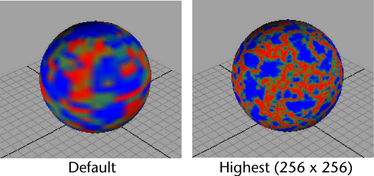
Lets you choose to view the textured object with varying degrees of accuracy and clarity.