


Learning Resources > Tutorials > Getting Started with Maya > Animation > Lesson 5: Inverse
kinematics >
Constraining an IK system
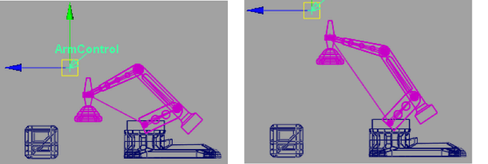
You can constrain the IK Handle to the control object (ArmControl) using a point constraint. A point constraint allows the transformation attributes of one object to be controlled by the transformations of another object. For example, you select and position ArmControl without having to touch the IK Handle. You also set the constraint so ArmControl maintains the current distance (offset) from the IK Handle. The offset ensures that the constrained IK handle doesn’t move to the same position as the control object.
To constrain the IK Handle to the control object
The order of selection when applying a constraint is important: you must select the constraining object first, and the item to be constrained second.
 .
.
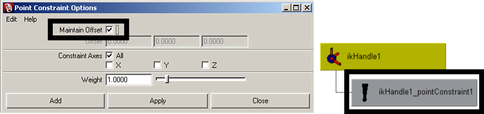
The IK handle is constrained to the control object. In the Hypergraph, a constraint node is created beneath the ikHandle1 node.
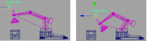
When you drag the manipulator, the control object moves, which in turn moves the IKHandle. Because the IK handle controls the skeleton and the mechanical arm model, they also move. The offset between the control object and the IK Handle is maintained.
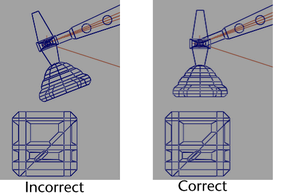
The Cargo Magnet does not continuously point downwards when rotated. Its orientation is based on the rotation it had in its original position.
The mechanical arm will be easier to pose if you set Cargo Magnet to be oriented downwards towards the floor of the scene regardless of the orientation of the other components of the arm.
You make CargoMagnet point downwards using an orient constraint. An orient constraint constrains the orientation (rotation) of the X, Y, and Z axes of one object to match those of the constraining (target) object.
In the next steps, you reset the position of the mechanical arm to its default position, and then apply an orient constraint to the last joint in the IK system so that its orientation matches the control object. The effect is that CargoMagnet points downwards regardless of any other movement in the scene.
To set the IK system to its default position

Zeroing the transformations on ArmControl resets the mechanical arm to its home position because of the freeze transformations step you performed in the previous section.
To apply an orient constraint for the IK system
.
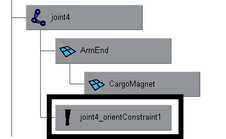
Joint4 is constrained to have the same orientation as the control object. In the Hypergraph, the constraint node is created below the joint4 node in the hierarchy.
CargoMagnet maintains an orientation facing the floor of the scene regardless of how the mechanical arm is positioned in the side view.
In the next section, you learn how to limit the range of movement for the IK system.