This topic will use diagrams to show how to use multiple geometry layers (class KFbxLayer) to create a layered texture (class KFbxLayeredTexture). A layered texture consists of several textures (class KFbxTexture) that are partially transparent, and that are overlaid to create a texture that is a blending of the original textures.
This topic also provides a visual review of geometry layers and geometry layer elements, two FBX concepts that were introduced in Applying Textures and Materials to Meshes. That section described a mesh in the shape of a cube.
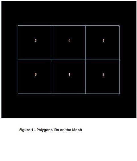
Here is a mesh in the form of a plane. Like the cube, it has six polygons, numbered 0 through 5:
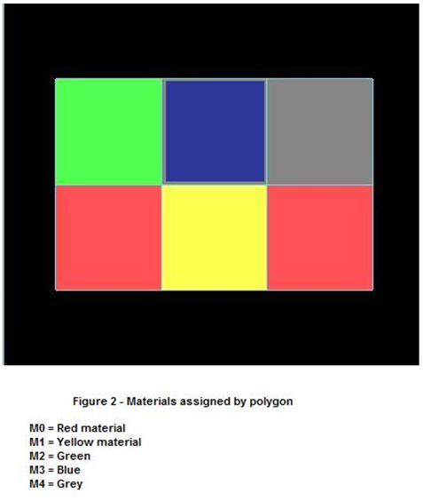
We have five materials (M0 through M4) that we want to apply to the six polygons. We’ll apply the red material M0 to polygons 0 and 2:
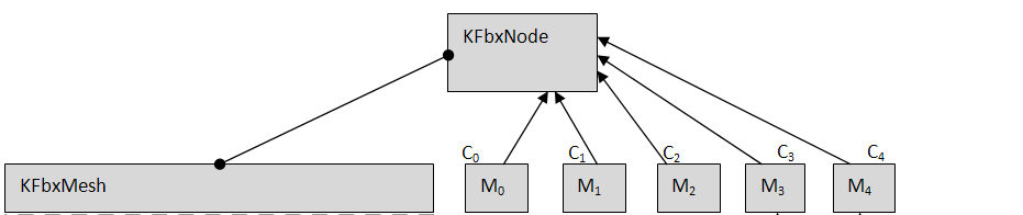
Let’s look at this in terms of FBX classes:
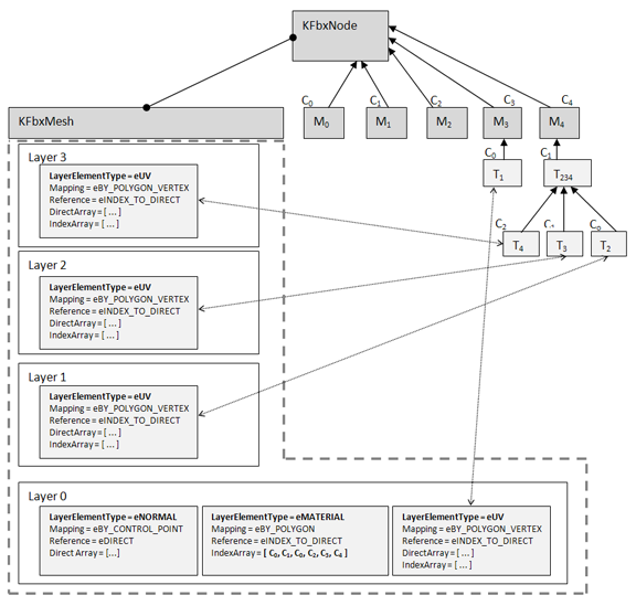
To do this, we create a geometry layer as a container for two geometry layer elements: normals and materials. The layer is Layer 0. We recommend that you use Layer 0 and only Layer 0, unless you have a particular reason for using another layer or layers. We’ll see a situation that requires multiple layers later on in this topic.
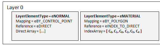
The normals for the 24 vertices (control points) are contained in a KFbxLayerElementNormal object. We’ll map the normals to the control points of the polygons. And we’ll use a DirectArray of 24 items, where each item is a KFbxVector4 object containing a normal. “Reference = eDIRECT” means that FBX SDK will refer to the elements of the DirectArray directly, i.e., without using an IndexArray.
We also need a KFbxLayerElementMaterial object, whose IndexArray contains the index numbers of connections. In our example, there are six elements in the IndexArray, one for each polygon in the mesh. Each IndexArray element contains the index number of the connection for that polygon. This maps the five connections (one connection for each of the five materials) to the six polygons of the mesh. The red material (M0) is applied to polygon 0 and polygon 2: that’s why C0 is in element #0 and element #2 of the IndexArray.
Now we want to go two steps farther:
When we are done, the mesh will look like this:
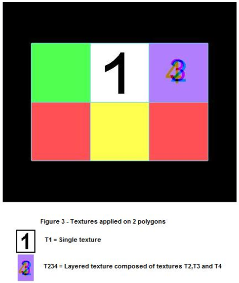
The textures with the number 1 is called T1. To apply the texture to polygon 4, we create a layer element for UVs in Layer 0. This layer element is an object of class KFbxLayerElementUV. And as you will see from the Figure 3, to apply texture T1 to polygon 4, we connect T1 to the material M3 (which is itself connected to polygon 4), and use the UVs to position the texture on the material.
The texture with number 2 is called T2. The texture with number 3 is called T3. The texture with number 4 is called T4. Each of these three textures needs a separate layer element (Layers 1, 2, and 3, respectively) so they can be blended together into a layered texture (class KFbxLayeredTexture).
Layered textures are an example of a case when you cannot use only Layer 0.
KFbxLayerElement::ELayerElementType is an enum that maps identifiers such as eUV, eNORMAL, and eMATERIAL to their corresponding classes (KFbxLayerElementUV, KFbxLayerElementNormal, KFbxLayerElementMaterial, ...). You must supply the enum as a parameter to KFbxLayer::GetLayerElementOfType().
KFbxLayerElement::EMappingMode is an enum that specifies how the layer element is mapped to the surface.
KFbxLayerElement::EReferenceMode is an enum that specifies how the IndexArray and DirectArray of a layer element are to be referenced.


