This rig enables you to perform modeling operations that are similar to “badging,” or deforming an otherwise flat feature onto a curved surface so that the output conforms to the shape of the curved surface.
This tool is a 3D texture mapping tool, where the idea of texture mapping is used to map a texture with thickness.
To place an object on another object
 The target geometry is accepted and given a pale green highlight.
The Conform operation takes the target geometry and, as if it was a thick stamp, applies it onto the destination surface. Initially, the targets are assumed to lie on the X-Y plane. This can be changed later after the rig has been set up.
After you have finished setting up the Conform Rig, you will see something like the following screen shot (in this example, the target is the round feature on the right; the destination is the half-cylinder surface on the left). The conformed target is shown applied on the destination, and had been deformed to fit the shape of the destination.
A gray plane is drawn immediately below the original input target, which represents the reference plane. In the center of the reference plane an X marks the contact point with respect to the reference plane. On the destination surface, a green point represents the location of the same contact point after the conform has been applied. A gray curve shows how the contact point from the reference plane is placed onto the destination.

By default, the Conform Rig preserves the size and length of your targets, and also the shape of your targets. The Conform Rig is designed to retain the shape of the footprint. You can see in the previous screen shot that the top of the target has been stretched. Later we will discuss the option to change that.
Inside the Conform Rig tool, you can adjust how the targets are mapped to the destination.
Using the GO buttons at the bottom of the modeling window, you can choose to be in translate, rotate, scale, or elevate mode.
Use the Translate mode to choose the position of the target with respect to the destination. Each set of targets defines a point called the contact point. When the rig is first set up, the contact point is positioned at the midpoint of the base of the bounding box of the targets. The translation is based on the contact point of your target. When the destination is an entire surface or a mesh or a set of stitchable surfaces, this contact point can be positioned at any point on the destination. Otherwise, if the destination is a surface curve, the contact point is constrained to move along the curve. If the destination is a single surface point, the target cannot be moved at all; however, if you move the surface point itself, the target follows.
Furthermore, if the destination is a surface curve, regular snapping (using one of the three tools) is available. You can snap the contact point to the associated curve division, curve intersection, and so on. Using the surface curve as the conform destination allows for precise placement of the target on the destination.
If there are parts of the target that extend beyond the ends of the destination, the tool extrapolates tangentially with respect to the destination:

To translate, click Translate button and click-drag along the destination surface — the target follows. While dragging, a bright green outline can be seen (the proxy, which is a lightweight approximation of your target). The proxy allows for real-time interactive update. The targets update for real when you release the mouse button. The green display for the contact point on the destination and the gray curve updates when you click-drag.

Use the Rotate mode to rotate the target about the contact point on the destination. Click-drag any mouse button to the left or right to adjust the angle. You can also type in the angle in relative (REL) or absolute (ABS) forms.
Use the Scale mode to adjust the size of the targets relative to the destination, using the contact point as the scale pivot. Again, if the target is scaled to extend beyond the destination, the tool extrapolates tangentially. Use the left mouse button to scale (click-drag to the left or right) the targets proportionally. Use the middle mouse to scale along the destination surface (making the target bigger but not thicker); use the right mouse button to scale how thick the target becomes.

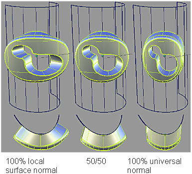
The surface on the right shows a tall version of the target, and also shows how conform works: by default, it uses the local surface normal to determine how to map the higher parts of the target, and for destinations that are very curved, this introduces distortions by stretching the top of the target because the normal directions diverge.
The Conform Control option window has a Parallel normal mode slider. If the value is 0.0 (as in the left objects of the next screenshot), you use 100% of the local normal of the destination. A value of 1.0 (on the right of the screenshot) means the normal of the destination found at the center of the target is used universally. The result is that the sides of the target appear parallel — hence the name. The default for this slider is 1.0. You can also use the slider to blend between the two effects (the middle objects in the screenshot use 0.5):

Use Elevate mode to choose to lift the targets up and away from the destination, or lower and sink the target into the surface. You can do so by click-dragging up and down in Elevate mode. You can also type in the elevation value in either absolute mode or relative mode, using the current linear unit.

The Conform tool respects the orientation of the destination surface. Initially, the target is conformed to the outward facing side of the surface (the side that shows as blue in the Orient Normals tool). If the target must be on the reverse side of the surface, click the Flip button, or click Revert and reverse the orientation of the surface before reapplying the Conform tool. Conform history does not react to changes in orientation made with the Orient Normals tool after the conform operation has been applied.
As mentioned before, the contact point serves as the pivot for the scale and rotate operations. It also defines the placement of the targets after conform. By default, the Conform tool puts the contact point at the center of the bottom of the targets.
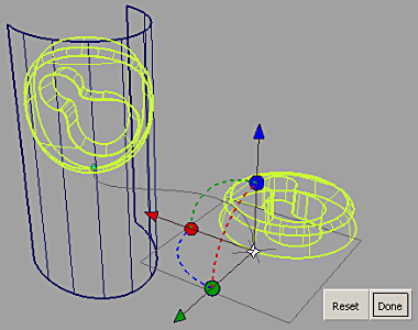
You can move the contact point. In the Conform Rig tool box, choose the Change Contact Point tool. After choosing this tool, you see something like the following:

Using the manipulator, you can move the contact point relative to the targets in their original position. As soon as you change the position of the contact point, the conformed targets update to show the effects of the change. You can also use the manipulator to snap the contact point to a particular point of the original target — click the light blue point at the center of the manipulator. After it turns white, you can use normal curve-snapping techniques to snap the contact point onto any part of the original targets, as shown here:

After you have moved the contact point, further rotation or scale operations within the Conform Rig tool will use the new position of the contact point as the pivot for the targets.
You can also change the orientation of the reference plane. The reference plane is initialized parallel to the XY plane. If your targets have a different orientation, the results of the conform operation may not make sense. Using the rotational handle of the manipulator allows you to rotate the reference plane to make a better fit with the original surface.
In the following screenshot, the target has been rotated so that the bottom no longer lies on the XY plane. If the rotated target is used in the Conform Rig tool as-is, the result of the conform operation is not what is expected. Using the Change Contact Point tool to rotate the reference plane fixes the problem without having to change the original target.


When targets are added to the rig, they are duplicated. The shape modifications are performed with these duplicated geometry. To restore the original geometry and to delete the modified geometry and history, click Revert. Notice that the manipulated modifiers do not return to their status before the dynamic modeling.

The fields in this section control the way the Conform Rig tool modifies the NURBS target surfaces. Settings in this window have no effect on meshes that were selected as targets. If all targets are meshes, or if Mesh Output is set, this section of the option window is hidden.
Choosing this mode enables you to determine how the edges of the target maps to the destination. If the value is 0.0, 100% of the local normal of the destination is used. A value of 1.0 means the normal of the destination found at the center of the target is used universally. The result is that the sides of the target appear parallel — hence the name. The default for this slider is 1.0. You can also use the slider to blend between the two effects.
The controls in this section can be used to adjust the output geometry.
If checked, any changes in any field in the control box or any tool operations lead to an automatic update of the model display. If Auto Recalc is not checked, click the Go button in the active window to update the display after any changes. Normally, if you have a very large model that takes a long time to update, you should leave the Auto Recalc box unchecked. Auto Recalc is checked on by default.

If Auto Recalc. is ON, the Go button is not shown. Any changes to the rig (options or constructors) causes the history to re-evaluate.
If Auto Recalc. is OFF, the Go button is displayed. Any changes to the rig cause the Go button to be enabled, and when you click Go the re-evaluation occurs. History itself exists the moment you enter the tool —not clicking the Go button does not change this, and you do not lose history by prematurely leaving the tool.
What you can do outside the tool afterwards:
If you are outside the tool after Conform Rig history is set up, you can modify the destination surface in any way, and the conformed targets update because of construction history. You can also modify the input target geometry and the conformed targets update accordingly.
Commit and Revert tools work the same as in the Transformer Rig and Lattice Rig.