


Alias includes a simple workflow to help you create valid output for rapid prototyping—.STL and .ZPR (Windows only) file formats.
Manifold, watertight meshes with consistent normals are required for successful rapid prototyping. Using this workflow, you can create valid output from a surface, a shell, a mesh, or any combination of these.
This workflow helps you stitch surfaces, tessellate shells, evaluate meshes for errors, and then repair the meshes, if necessary, before exporting to .STL or .ZPR file formats.
To create and export valid output from surfaces
The surfaces are stitched. The prompt line indicates how many shells were created and the number of unmatched boundaries found, if any.

Open boundaries are highlighted and small arrows point to problem areas on the model.
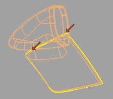
If the shell is a closed volume (0 boundaries), proceed to step #5.
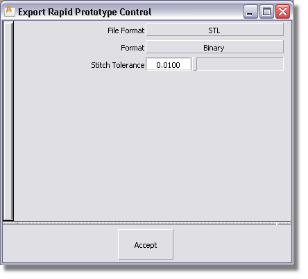
To close any open boundaries, adjust the Stitch Tolerance value and click Recalc..Stitch Tolerance determines which boundaries will be stitched together when you recalculate. If two boundaries are further apart than this value at some point, they are not stitched there.
If the shell still has open boundaries, re-adjust the Stitch Tolerance value and click Recalc.. Repeat until you cannot reduce the number of open boundaries any further.
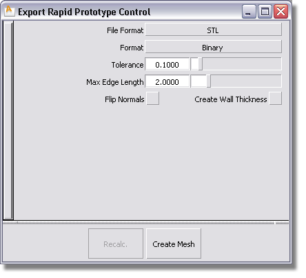
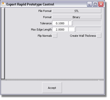
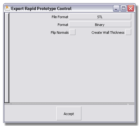
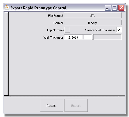
The options change in the Export Rapid Prototype Control dialog box.
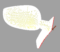
The shell is tessellated based on the settings in the dialog box. The prompt line indicates how many meshes were created, the number of polygons, and the number of boundaries found.

The tessellated model displays with normal orientation shading in flat shaded mode. Normal orientation is set automatically based on external visible parts of the model being in the positive direction. Open boundaries are highlighted and small arrows point to problem areas on the model.
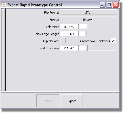
Tolerance – Controls how accurately surfaces are tessellated. The lower the value, the greater the number of triangles. This value will be reflected in the resolution of the physical model that will be produced by the rapid prototyping technology.
Max Edge Length – Specifies the maximum length of any triangle edge (in current linear units).
The shell is retessellated based on the set values.
The mesh offset updates. Repeat until you have a solid mesh.
STL – If you select STL, select the Format of the file (ASCII or Binary).
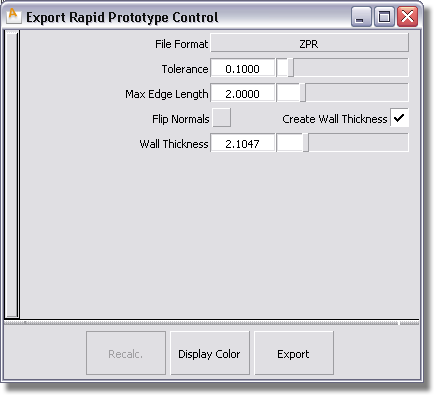
ZPR (Windows only) – If you select ZPR, the Display Color button appears on the Export Rapid Protype Control dialog box.
To create and export valid output from a shell
The shell is tessellated based on the settings in the dialog box. The prompt line indicates how many meshes were created, the number of polygons, and the number of boundaries found.
The tessellated model displays with normal orientation shading in flat shaded mode. Normal orientation is set automatically based on external visible parts of the model being in the positive direction. Open boundaries are highlighted and small arrows point to problem areas on the model.
Tolerance – Controls how accurately surfaces are tessellated. The lower the value, the greater the number of triangles. This value will be reflected in the resolution of the physical model that will be produced by the rapid prototyping technology.
Max Edge Length – Specifies the maximum length of any triangle edge (in current linear units).
The shell is retessellated based on the set values.
The mesh offset updates. Repeat until you have a solid mesh.
STL – If you select STL, select the Format of the file (ASCII or Binary).
ZPR (Windows only) – If you select ZPR, the Display Color button appears on the Export Rapid Protype Control dialog box.
To create and export valid output from a mesh
The prompt line indicates the number of meshes, polygons, and boundaries found. Small arrows point to open boundaries on the model so you can quickly identify problem areas.
The mesh offset updates. Repeat until you have a solid mesh.
STL – If you select STL, select the Format of the file (ASCII or Binary).
ZPR (Windows only) – If you select ZPR, the Display Color button appears on the Export Rapid Protype Control dialog box.
