IGES (Initial Graphics Exchange Specification) is a data exchange format between CAD/CAM systems.
When storing an IGES file, the following options are available:
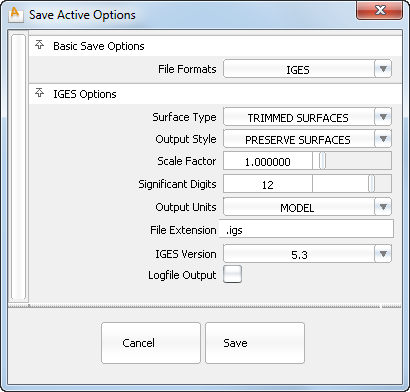
Curves and surfaces are written to IGES as NURBS curves and surfaces. Layer Number information is exported as IGES Level information and can be recognized by each IGES entity. Alias Set information is not exported.
Determines whether trimmed surfaces are written as trimmed or bounded. The default is TRIMMED SURFACES.
Lets you preserve surfaces or convert them to curves for some drafting packages. If you choose CONVERT TO CURVES to convert surfaces to curves and have set the patch precision to a number greater than the default, all isoparametric curves are stored in the file. The default is PRESERVE SURFACES.
Lets you save the wire model at a scale other than it was constructed. 1.0 is the default value.
The number of significant digits for coordinate data in the exported file can be specified in this field. The minimum number is 1 and the maximum number is 15.
Lets you choose any of the data unit types supported by the IGES standard, including miles, feet, inches, mils, microinches, kilometers, meters, centimeters, millimeters, and microns. The exported coordinate data is converted from the current linear units set in Alias to the units selected here.
An additional choice is available called MODEL, which keeps the output units in the exported file the same as the linear units in Alias (IGES option only).
Some receiving systems require that CAD files have a specific filename extension before they can be recognized. The filename extension specified here is automatically appended to the filename of the exported file. The default is.igs.
When ON, a logfile containing a list of path names of exported files, and a list of warning and/or error messages, is generated. The default is OFF.
If you create in Alias a surface of revolution with negative angle sweep (the starting angle or/and angle negative) this surface of revolution will be exported to IGES format as a NURBS Surface (IGES entity type 128) and not an IGES Surface of Revolution (IGES entity type 120).
IGES/VDAIS output environment variables option definitions
When set to 1 (default), 3D points are output. When set to 0, 3D points are not output.
When set to 1 (default), curves are output. When set to 0, curves are not output.
When set to 1 (default), surfaces are output. When set to 0, surfaces are not output.
When set to 1 (default), faces (trimmed surfaces) and shells are output. When set to 0, they are not output.
When set to 1 (default), invisible geometry is output. When set to 0, invisible geometry is not output.
When IGES_OUT_SPLINE_TYPE is set to 0 (B-Spline), this variable controls the type of IGES entity used for multi-span linear (that is, polyline) trim curves.
When set to 1, linear trim curves are output as IGES entity type 106 form 12 Copious Data. When set to 0, linear trim curves are output as IGES entity type 126 Rational B-spline Curves.
Changes the number of digits of double precision stored in IGES or VDAIS files produced by Alias. The default is 12 digits of precision, but can be changed to any number between 1 and 15.
Setting this variable to 1 specifies the output of 2D parametric trim curves only. The default of 0 outputs both 2D and 3D trim curves. Setting this value to 2 specifies the output of model space trim curves only.
When set to 1, both 3D model space and 2D parametric space boundary curves are output if the Surface Type option has been set to BOUNDED SURFACE. When set to 0, only model space boundary curves are saved in the IGES or VDAIS file.
This variable produces polygon data from arbitrary degree curves and surfaces for the IGES or VDAIS format.
When set to 1 and used in conjunction with the CONVERT TO CURVES option:
When set to 1 and used in conjunction with the PRESERVE SURFACE option:
 .
.
Setting this variable to 1 causes all untrimmed surfaces to be output as trimmed surfaces. The default of 0 produces no change in surface output.
With the default of 1, Alias instances are output as transformed copies of the geometry that they instance. When set to 0, Alias instances are not stored.
With the default of 0, multi-span linear spline curves (polylines) are output as copious data IGES entities (106), and when set to 1, as IGES entity Rational B-spline curve (126), or the IGES/VDAIS Output Style option.
When set to 1, surfaces are converted to curves. With the default of 0, surfaces are preserved in the IGES or VDAIS file. The value of this variable is reflected in the IGES or VDAIS Output Style option.
With the default of 0, Alias trimmed surfaces are written as IGES entity 144 and curves on surface are written as IGES entity 142.
When set to 1, trimmed surfaces are written as IGES Bounded Surface entities (143), and curves on surface are written as IGES Boundary entities (141). The value of this variable is reflected in the IGES or VDAIS Surface Type option.
This variable controls the output of 2D parametric space trim curves. When set to 1, 2D parametric space trim curves are output in monotone increasing/decreasing pieces. When set to 0, these trim curves are output whole.
When set to 1, all 2D parametric space trim curves are degree raised to cubic if necessary. When set to 0, these trim curves may be of degree 1, 2 or 3.
When set to 0, linear 2D parametric space trim curves that lie on a natural surface boundary are output as IGES entity type 110 Line. When set to 1, these curves are output as linear b-splines in the form of IGES entity type 126 Rational B-Spline Curve, or the IGES/VDAIS Spline Type option.
Controls the value of the “PREF” flag (preferred representation in sending system) of IGES entity type 142 Curve on a Parametric Surface. Some receiving systems require a specific value for this field. The set of values for this variable correspond to the valid range of values for the “PREF” flag.
The values are: 0 = Unspecified; 1 = 2D parameter space curve; 2 = Model Space Curve; 3 = Both 3D and 2D curves equally preferred.
When set to 0, degenerate 3D model space trim curves (that occur at the poles and seams of periodic geometry) are removed from trim boundaries before these boundaries are output to IGES or VDAIS.
When set to 1, degenerate 3D model space trim curves are not removed (0=none, 1=poles, 2=seams, 3=poles and seams).
This variable specifies the scale factor applied to the wire model when it is exported. The default is 1.
When set to 1, degenerate 3D model space trim curves are not removed (0=none, 1=poles, 2=seams, 3=poles and seams).
This variable controls the version of IGES used for the output file. When set to “6,” the output file conforms to IGES V4.0. When set to 8, the output file conforms to IGES V5.0. When set to 11, the output file conforms to IGES v5.3. No other versions of IGES are supported on output (this parameter is not applicable for VDAIS). For VDAIS files, this variable always has a value of 6.
This variable controls the units of measure used for the model in the output file.The valid ranges of values for units are:
| Value | Unit | Value | Unit |
|---|---|---|---|
| 1 | Inches | 7 | Kilometers |
| 2 | Millimeters | 8 | Mils |
| 3 | Model | 9 | Microns |
| 4 | Feet | 10 | Centimeters |
| 5 | Miles | 11 | Microinches |
| 6 | Meters |
No other units are supported. If set to 3, then the linear units set in the Alias modeler are used. For VDAIS compatibility, this parameter is ignored since the units must be millimeters.
This variable specifies the output file type: 1 = IGES (default), 2 = VDAIS, 3 = JAMAIS, 4 = C4.
This variable specifies what the file extension of the output file will be. It can be set as anything valid for UNIX, but the value must begin with a '.'. For example, some systems require “.igs”. If the value is invalid or not present, the default “.igs” is used.


