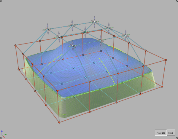
If, after setting up
a Transformer Rig and clicking Go, the surfaces
do not update as expected,
- Check to see if the rig was set up properly.
- check to see if target surfaces are drawn
using dashed lines: that is how the tool indicates there is an error
in the calculations.
- The first setup might not be the best:
try modifying the rig and recalculate to see if the results are
improved.
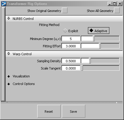
- Try the options in the current selected
Fitting Method.
- increasing the values in the options
tends to give you a more accurate result which takes longer to compute
- Try the other Fitting Method.
Each case is different
— it all depends on the geometry and the intent. As you gain experience
using the tool, you will develop a better feel for which method
works best.
- Draw Correspondence gives visual feedback
as to whether there are conflicts in the rig, as a result of interfering
modifiers and constraints. The visualization is green where there
is no conflict, and graduates from green to yellow to red to show
regions of conflict. This is a good diagnostic tool when the shape
modification behaves wildly.
In the following image, the modifier and the
constraint intersect. Notice that close to the intersection point,
the visualization turns from green to yellow to red, to indicate that
there is a conflict.
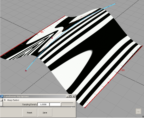
- The Sampling Density field controls quality
and speed. A low value results in faster updates, but may introduce
quality problems. A higher value results in a more faithful shape
modification, but increases the update time. The following images
show how artifacts are introduced when sampling is too low, and
how they can be avoided with a higher sampling rate.
- Several factors may contribute to undesirable
shape artifacts. They have been discussed above, and may include
inappropriate NURBS fitting, low sampling density, and conflicts
between constraints,modifiers, and clampers. To rule out inappropriate NURBS
fitting, try toggling Mesh Output and seeing whether artifacts are
affected. To rule out sampling density, try a higher sampling density
setting.
- After setting up a Lattice Rig, the rig
may be partially or totally locked.
- If you are modifying trimmed surfaces,
the part of the lattice that intersects with the discarded portions
of the trimmed surfaces is locked. In this case, shrink the trim
surface with the shrinkToTrim plug-in.
- If you are modifying NURBS surfaces that
protrude from the lattice, the outside portions may be modified.
This is due to the global effects of NURBS fitting. If you want to
reduce these effects, increase the number of spans. To eliminate
them entirely, you may have to switch to Mesh Output.
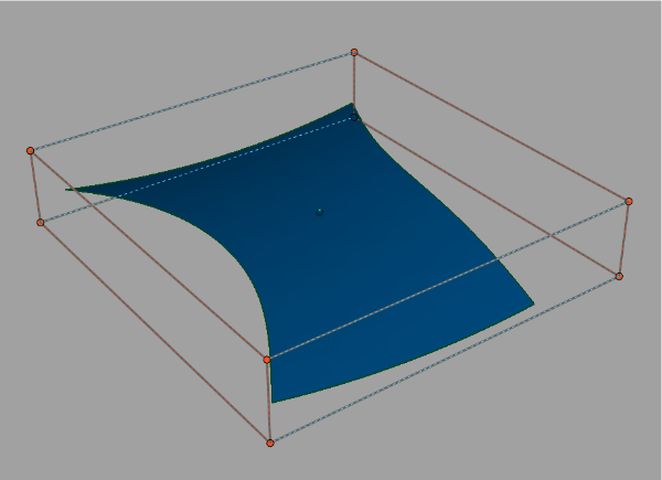
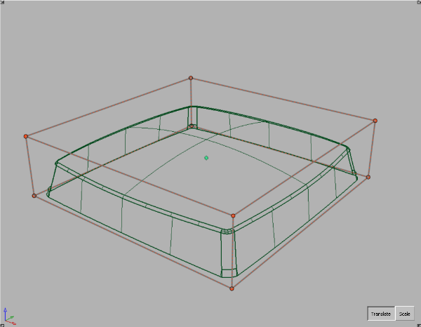
- When the Lattice Rig is applied to this
surface, the two sides of the lattice are locked, with no obvious
reasons.
If you turn on the CVs of the surface, you see
that the surface is a trimmed surface, and the removed parts intersect
with the lattice.
Shrinking the trim will fix this problem.
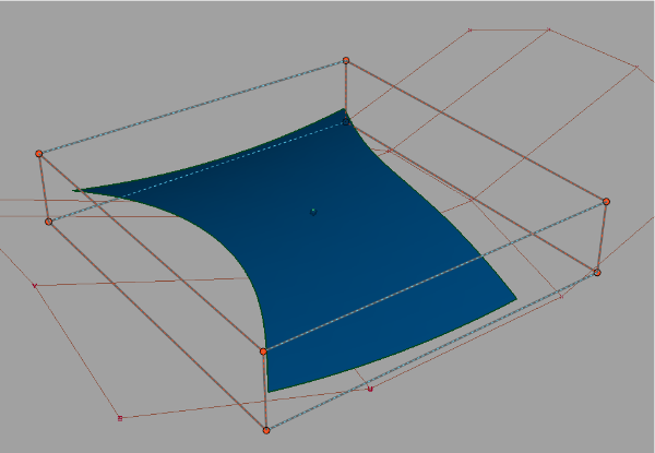
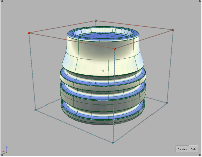
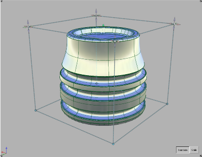
- The Lattice rig may be too close to the
surface. In these cases, move or scale the lattice away from the
target geometry. In this example, the initial lattice is too close
to the top of the target.
Translating the top of the lattice upwards solves
the problem.
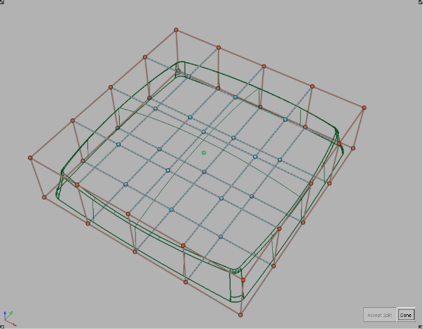
- Refine the lattice using the Split
Edge tool to give it more degrees of freedom.
