![]()
Checks curvature on curves and surfaces with combs and min/max locators.
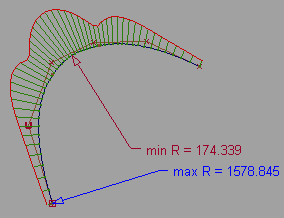
Use the curvature icon to view and modify curvature combs. You can view a curvature comb on a curve, or on a surface in the U and V directions.

Curvature combs can also be displayed on a surface cross sections through the Cross Section Editor options. See Windows > Editors > Cross Section Editor.
To view a surface curvature as a color map on the surface, use the Curvature Evaluation mode under Diagnostic Shading on the Control Panel.
See Curvature Evaluation.
To see the curvature options (at the bottom
of the Control Panel), first select a curve or surface, then click
the Curvature  icon in the Modeling Control
Panel.
 tool (in addition to options
located in the tool’s own option box).

This option scales the length of the curvature combs.
It also applies to the curvature combs on cross sections.
The sampling density per curve, that is the number of quills on a curvature comb. Increasing the samples results in a finer curvature comb.
This option also applies to the curvature combs on cross sections.
This option only applies to surfaces.
Length – Evenly space the curvature combs along the length of the surface (in U or V direction). The numbers of combs (for U and V respectively) are given by the values typed in the Number text fields.
Parameter – Place the curvature combs only on isoparametric curves (in U and V direction).
Set the number of curvature combs on the surface in each direction.
Click the check boxes to turn on or off locators displaying the points of Minimum and Maximum radius of curvature. These correspond to the points of maximum and minimum curvature respectively.